
Ham Radio Technician License study guide · Lesson 14 of 15
Antennas and Feed Lines
Antenna types, polarization and gain · Feed lines, standing waves and connectors
This is the lesson's study guide from the FlashFeed app, plus its key facts and a self-test.
What you'll be able to do
- Explain antenna polarization, gain and loading, and identify which antenna types give the most gain
- Describe how length sets resonant frequency and how common portable, mobile and dipole antennas perform
- Identify the usual impedance of coax and why it is the most common feed line, the main connectors and their weatherproofing, and how feed lines compare
- Explain SWR, feed line loss and the role of an antenna tuner, and name causes of loss and SWR changes
Every station depends on its antenna and on the feed line that carries the signal to it. This lesson covers what makes an antenna concentrate a signal, how antenna length relates to frequency, and how handheld and mobile antennas behave. It then covers the cable and connectors that join the radio to the antenna, and the measure of how well the two are matched. A new licensee needs these ideas to choose equipment sensibly and to spot why a station is performing poorly.
Antenna types, polarization and gain
Beam antennas and gain
A beam antenna is an antenna that concentrates signals in one direction. It simply favors one direction over the others.
Antenna gain is the increase in signal strength in a specified direction compared to a reference antenna. It describes how much stronger the signal is in a chosen direction than it would be from the reference antenna.
Among a 5/8 wave vertical, an isotropic antenna (a theoretical reference that radiates equally in all directions), a J pole and a Yagi, the Yagi offers the greatest gain. A new licensee who wants the most signal toward a distant station would therefore pick the Yagi.
Polarization and loading
The polarization of an antenna is described by the orientation of its electric field.
Antenna loading is a way of electrically lengthening an antenna by inserting inductors in its radiating elements. The antenna behaves as though it were longer than its physical size.
Length and resonant frequency
Length and resonant frequency are tied together. Shortening a dipole antenna increases its resonant frequency.
A familiar case is the 19-inch-long vertical antenna often used on 2 meters. It works there because it is a resonant quarter-wave.
Handheld and mobile antennas
A handheld radio transceiver usually carries a short flexible antenna. Compared with a full-sized quarter-wave antenna, its disadvantage is low efficiency.
Using a handheld very high frequency (VHF) transceiver inside a vehicle with no externally mounted antenna has its own drawback. Signal strength is reduced by the shielding effect of the vehicle.
For VHF or ultra high frequency (UHF) mobile service, a 5/8-wavelength whip has an advantage over a 1/4-wave antenna: it has more gain.
The dipole pattern
A half-wave dipole antenna radiates its strongest signal broadside to the antenna. A station placed broadside to a dipole gets the strongest signal, and a station off the ends gets less.
Sources
Feed lines, standing waves and connectors
Coaxial cable
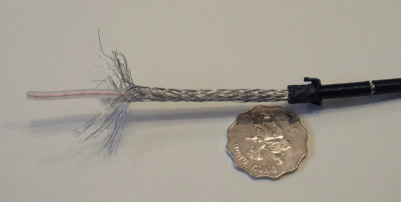
The most common impedance of coaxial cable (coax) used in amateur radio is 50 ohms.
Coax is the most common feed line for amateur antenna systems because it is easy to use and requires few special installation considerations.
Loss in coax
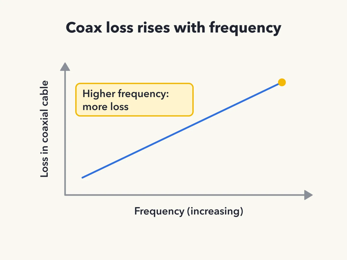
As the frequency of a signal in coaxial cable increases, the loss increases.
Loss in a coaxial feed line comes from each of these sources:
- water intrusion into coaxial connectors;
- high standing wave ratio (SWR);
- multiple connectors in the line.
Comparing feed lines
Two common coaxial cables differ electrically in their loss. RG-213 cable has less loss at a given frequency than RG-58.
Among the feed lines listed (50-ohm flexible coax, multi-conductor unbalanced cable, 75-ohm flexible coax and air-insulated hardline), air-insulated hardline has the lowest loss.
Connectors
Three connector types should be carefully taped for weather protection when used outdoors:
- PL259;
- Bayonet Neill-Concelman (BNC);
- Type N.
The PL-259 is commonly used at HF (high frequency) and VHF frequencies. Because it is not watertight, a PL-259 outdoors needs its tape.
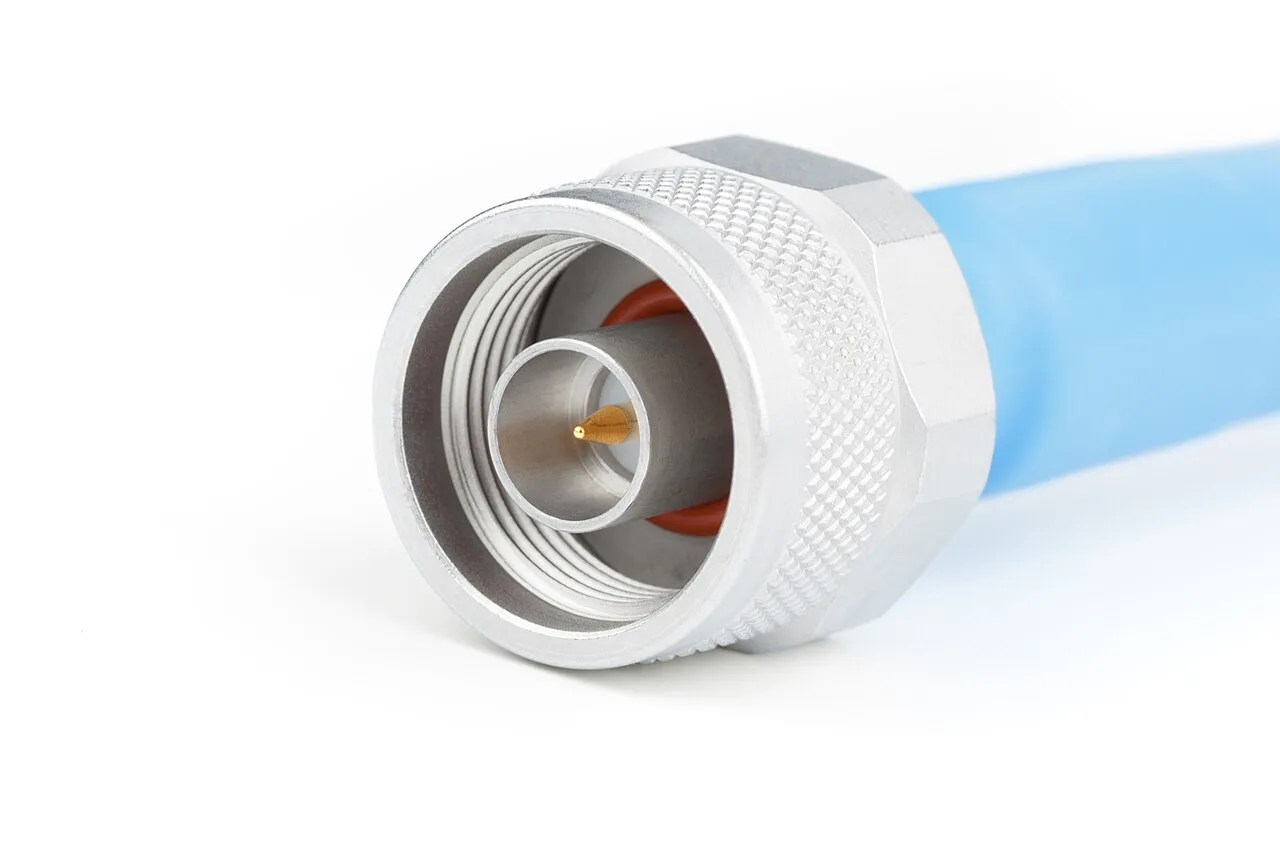
For frequencies above 400 megahertz (MHz), the Type N is the most suitable radio frequency (RF) connector.
SWR and antenna tuners
Standing wave ratio (SWR) is a measure of how well a load is matched to a transmission line.
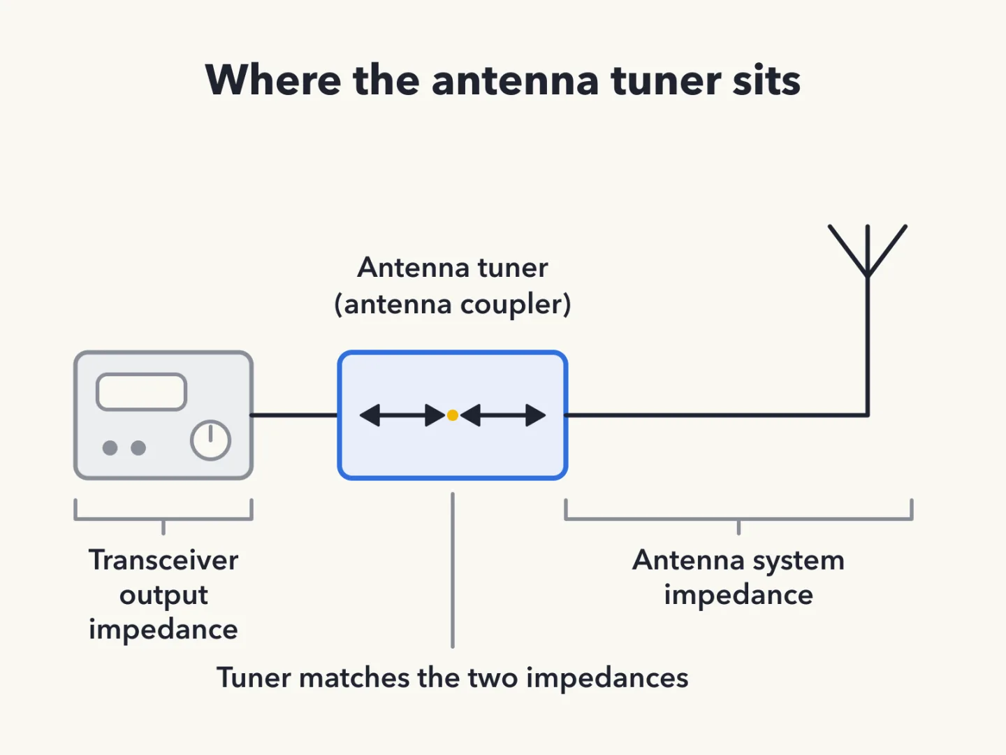
An antenna tuner, also called an antenna coupler, has one major function. It matches the antenna system impedance to the transceiver's output impedance.
Erratic SWR
A loose connection in the antenna or feed line can cause erratic changes in SWR. When the reading jumps around, the connections in the antenna and feed line are the place to look.
Sources
Key facts
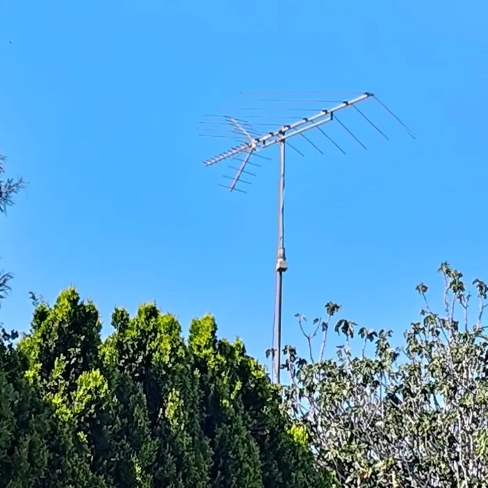
What a beam antenna does
A beam antenna concentrates signals in one direction. It favors one direction over the others.
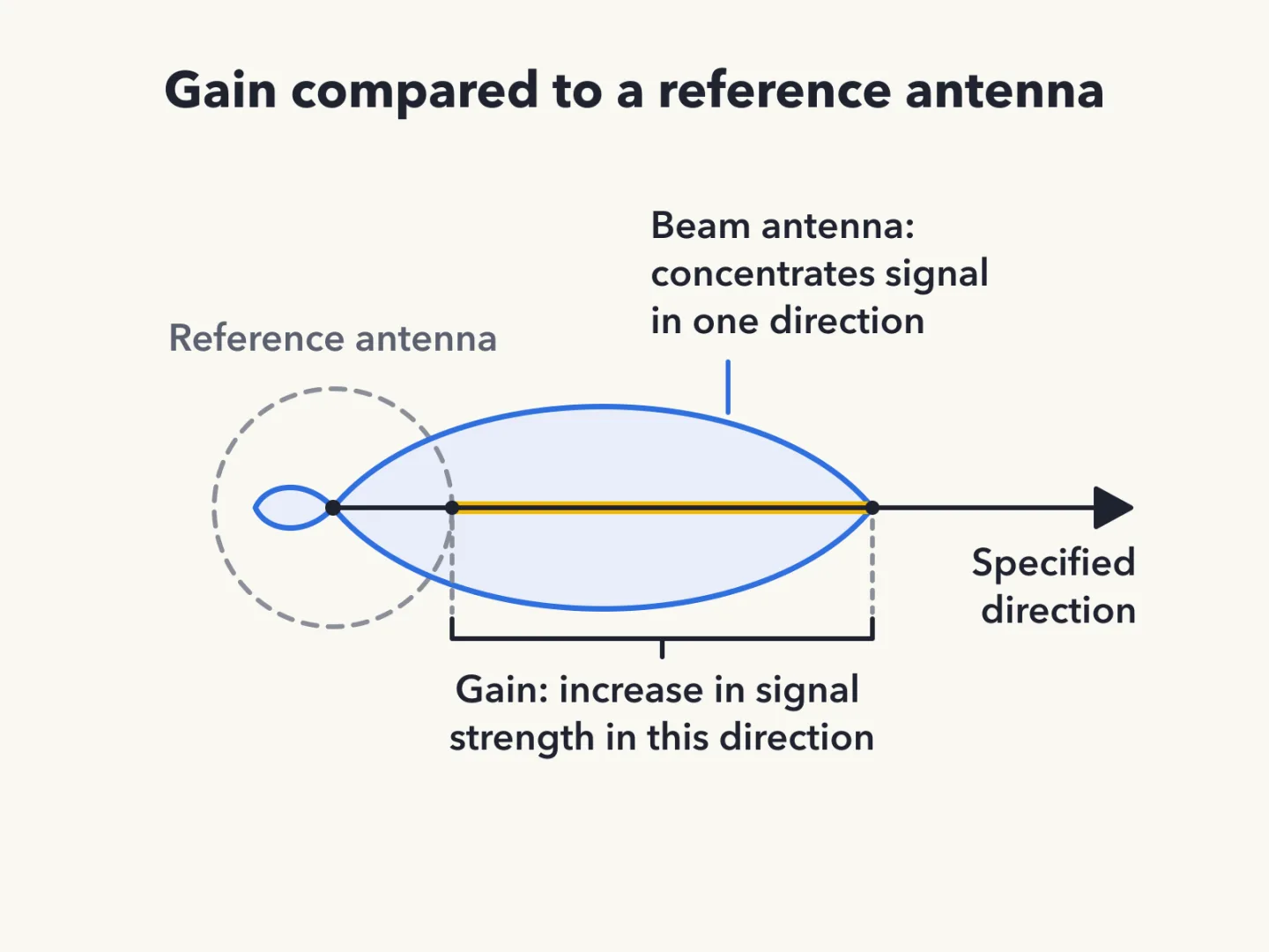
Antenna gain defined
Antenna gain is the increase in signal strength in a specified direction compared to a reference antenna. It describes how much stronger the signal is in a chosen direction.
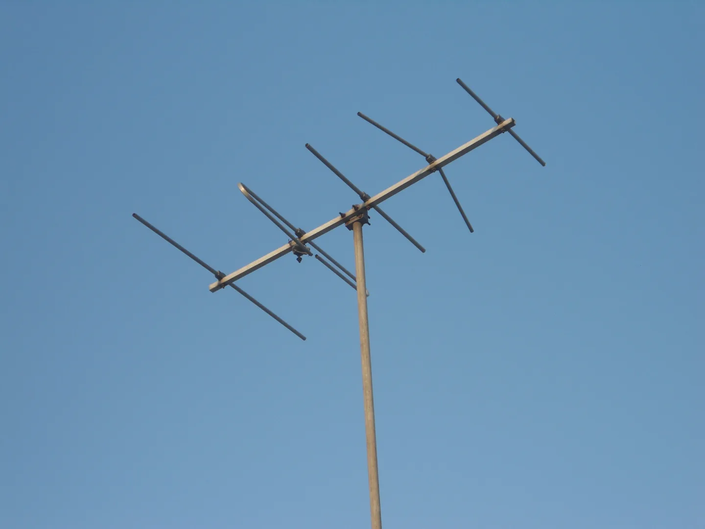
The Yagi has the most gain
Among a 5/8 wave vertical, an isotropic antenna, a J pole and a Yagi, the Yagi offers the greatest gain. It is the pick for the most signal toward a distant station.
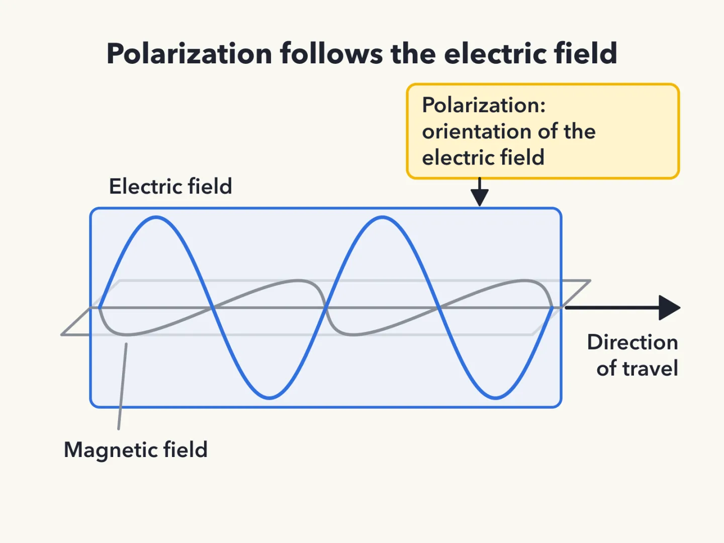
How polarization is described
The polarization of an antenna is described by the orientation of its electric field.
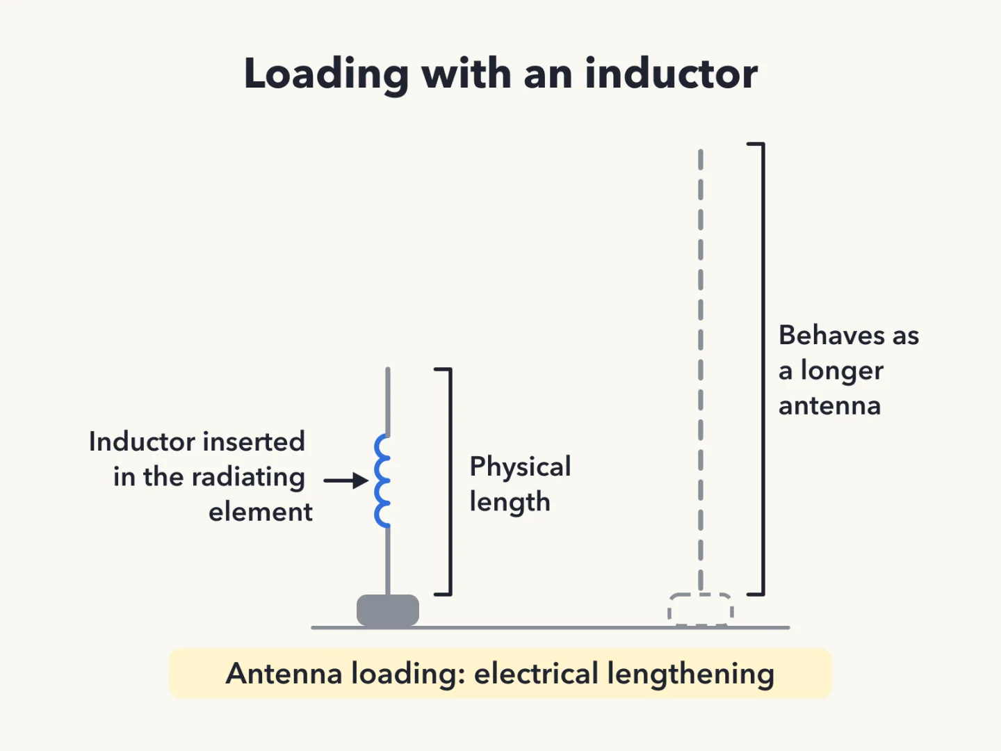
Antenna loading explained
Antenna loading is a way of electrically lengthening an antenna by inserting inductors in its radiating elements. The antenna then behaves as though it were longer than its physical size.
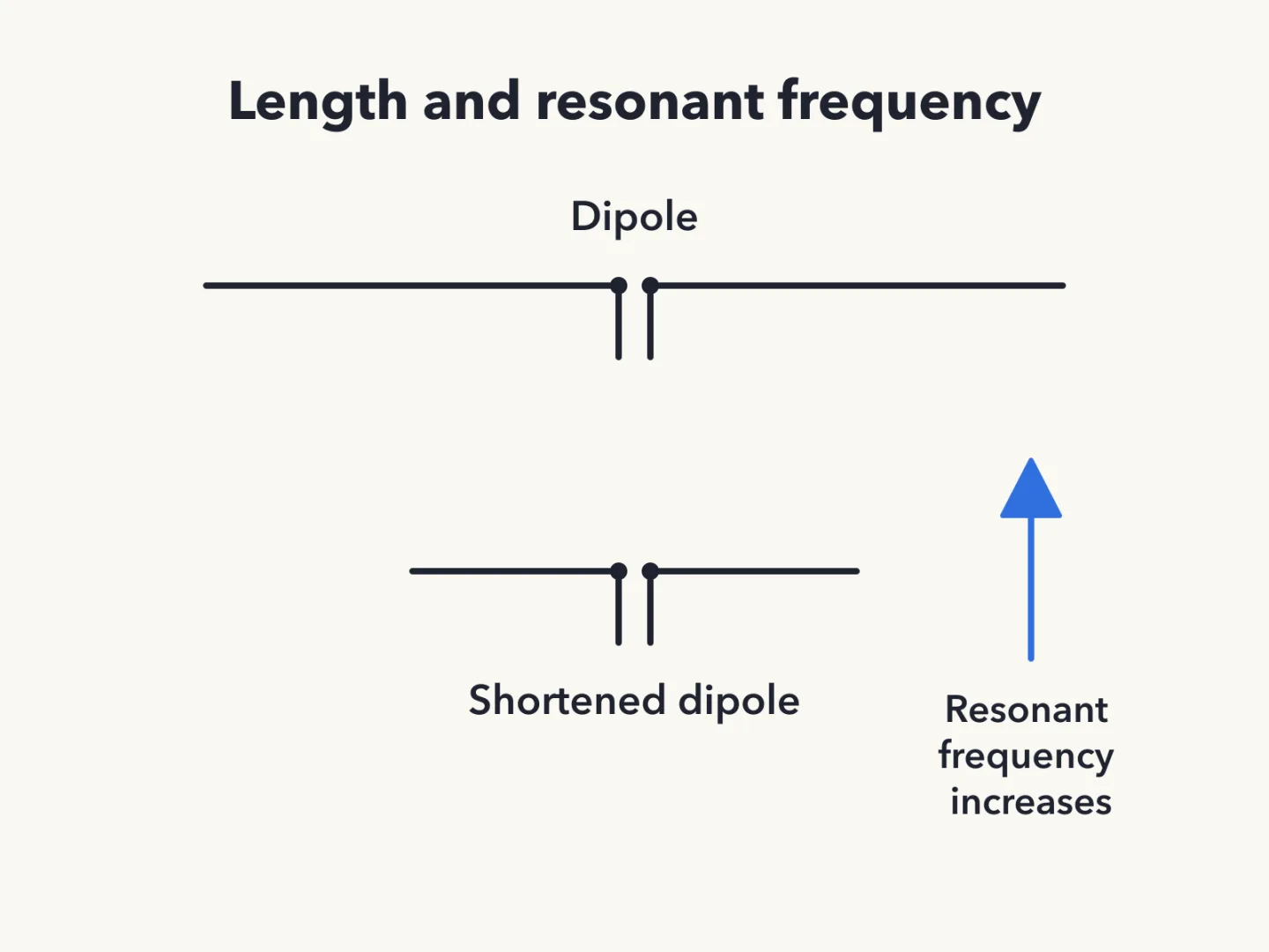
Shorter dipole, higher frequency
Shortening a dipole antenna increases its resonant frequency.
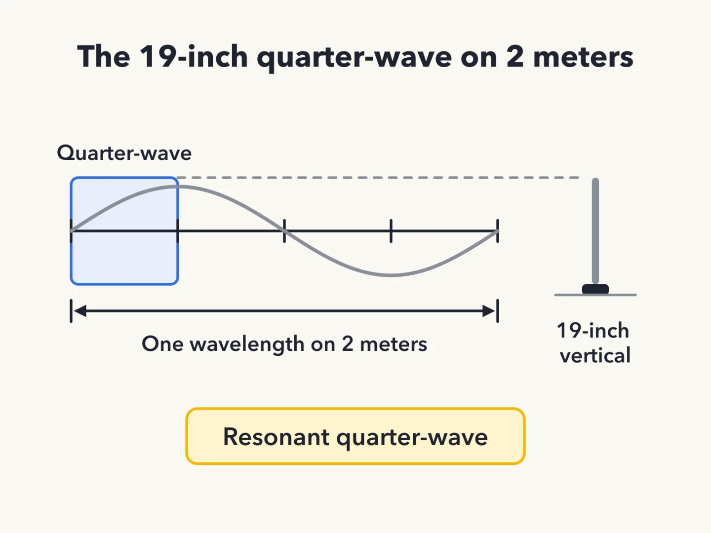
The 19-inch 2-meter vertical
A 19-inch-long vertical antenna is often used on 2 meters because it is a resonant quarter-wave.
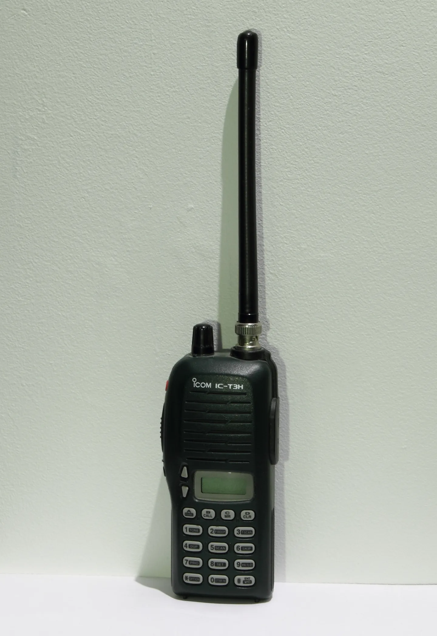
The handheld's short antenna
A handheld transceiver's short flexible antenna has low efficiency compared with a full-sized quarter-wave antenna.
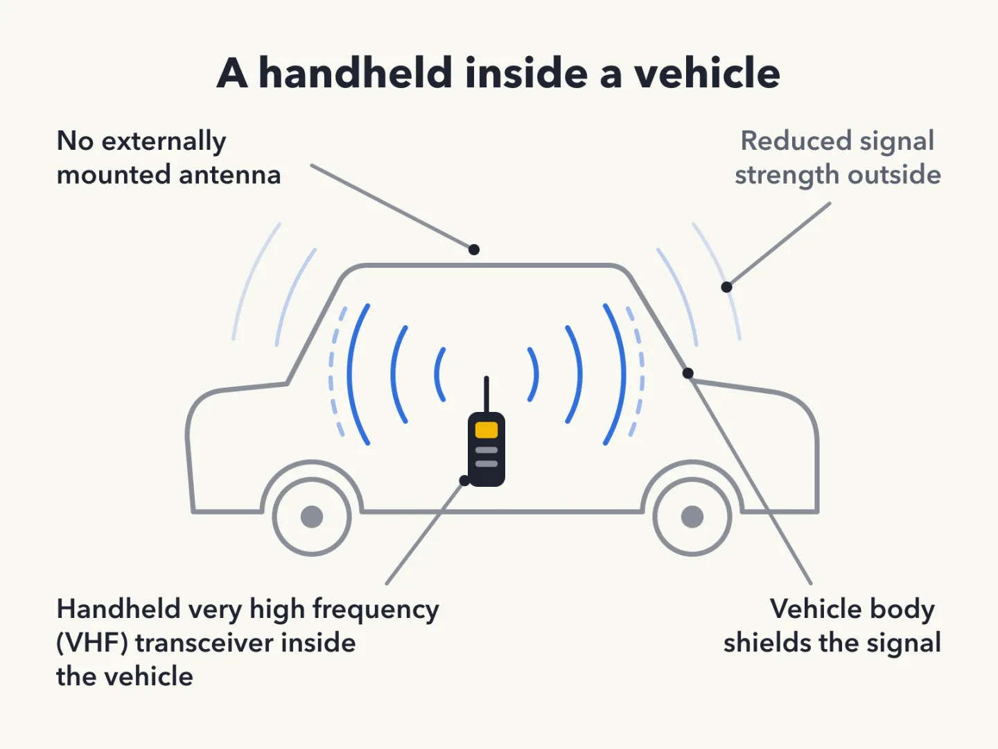
Handheld inside a vehicle
Using a handheld very high frequency (VHF) transceiver inside a vehicle with no externally mounted antenna has a drawback. Signal strength is reduced by the shielding effect of the vehicle.
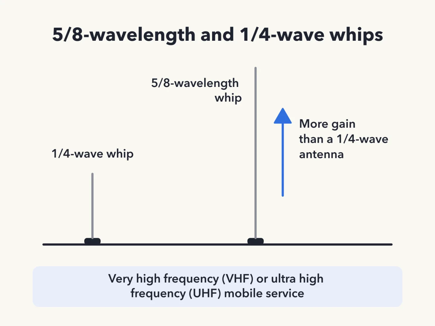
Why a 5/8-wavelength whip
For very high frequency (VHF) or ultra high frequency (UHF) mobile service, a 5/8-wavelength whip has more gain than a 1/4-wave antenna.
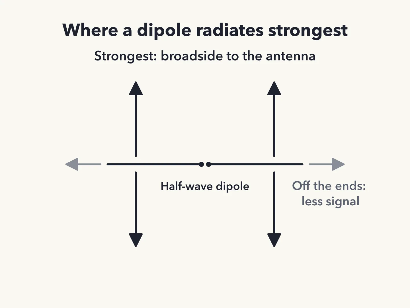
Where a dipole radiates most
A half-wave dipole radiates its strongest signal broadside to the antenna.
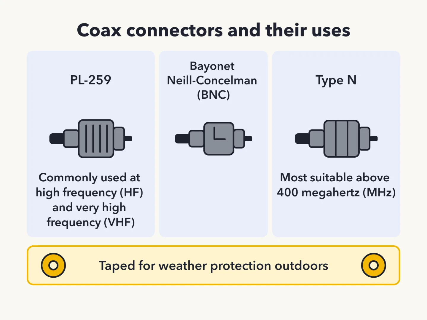
Taping connectors outdoors
PL259, Bayonet Neill-Concelman (BNC) and Type N connectors should all be carefully taped for weather protection when used outdoors.
Common coax impedance
The most common impedance of coaxial cable (coax) used in amateur radio is 50 ohms.
Why coax is so common
Coax is the most common feed line for amateur antenna systems because it is easy to use and needs few special installation considerations.
What standing wave ratio means
Standing wave ratio (SWR) is a measure of how well a load is matched to a transmission line.
What an antenna tuner does
An antenna tuner, or antenna coupler, matches the antenna system impedance to the transceiver's output impedance.
Coax loss rises with frequency
As the frequency of a signal in coaxial cable increases, the loss increases.
Type N above 400 megahertz
For frequencies above 400 megahertz (MHz), the Type N is the most suitable radio frequency (RF) connector.
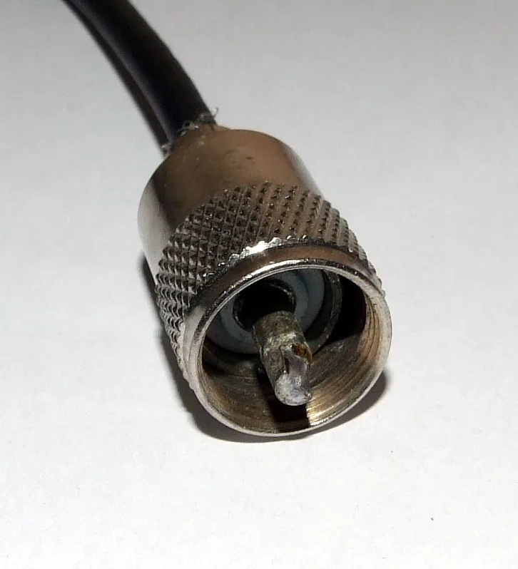
Where the PL-259 is used
The PL-259 is commonly used at high frequency (HF) and very high frequency (VHF) frequencies. Because it is not watertight, it needs tape outdoors.
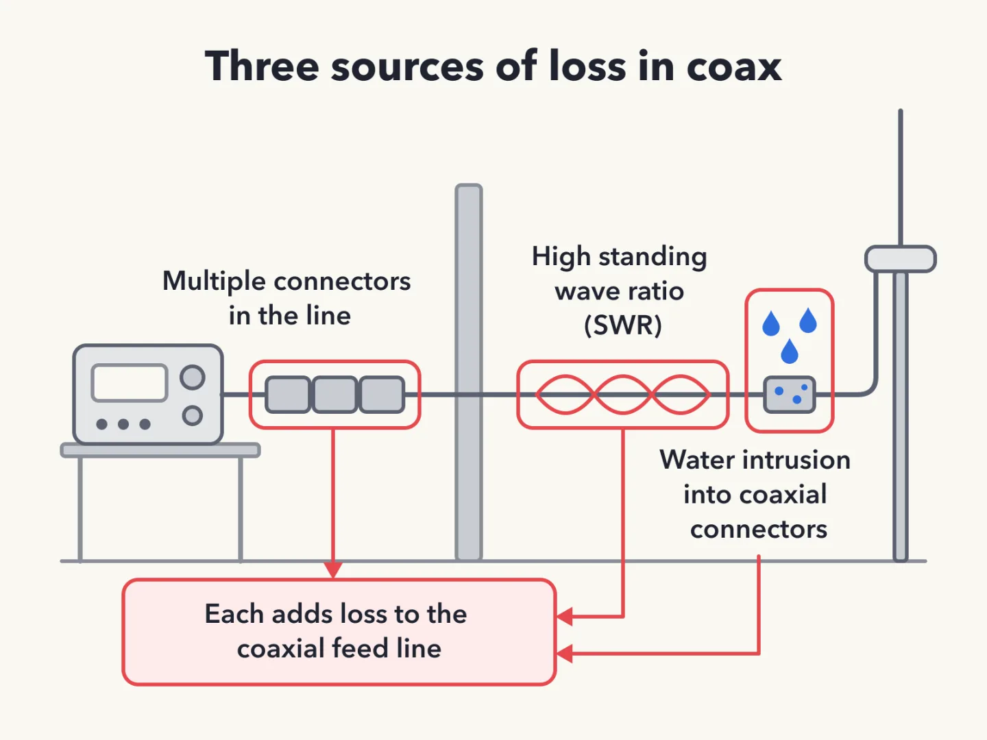
Sources of loss in coax
Three things add loss to a coaxial feed line: water intrusion into coaxial connectors, high standing wave ratio (SWR), and multiple connectors in the line.
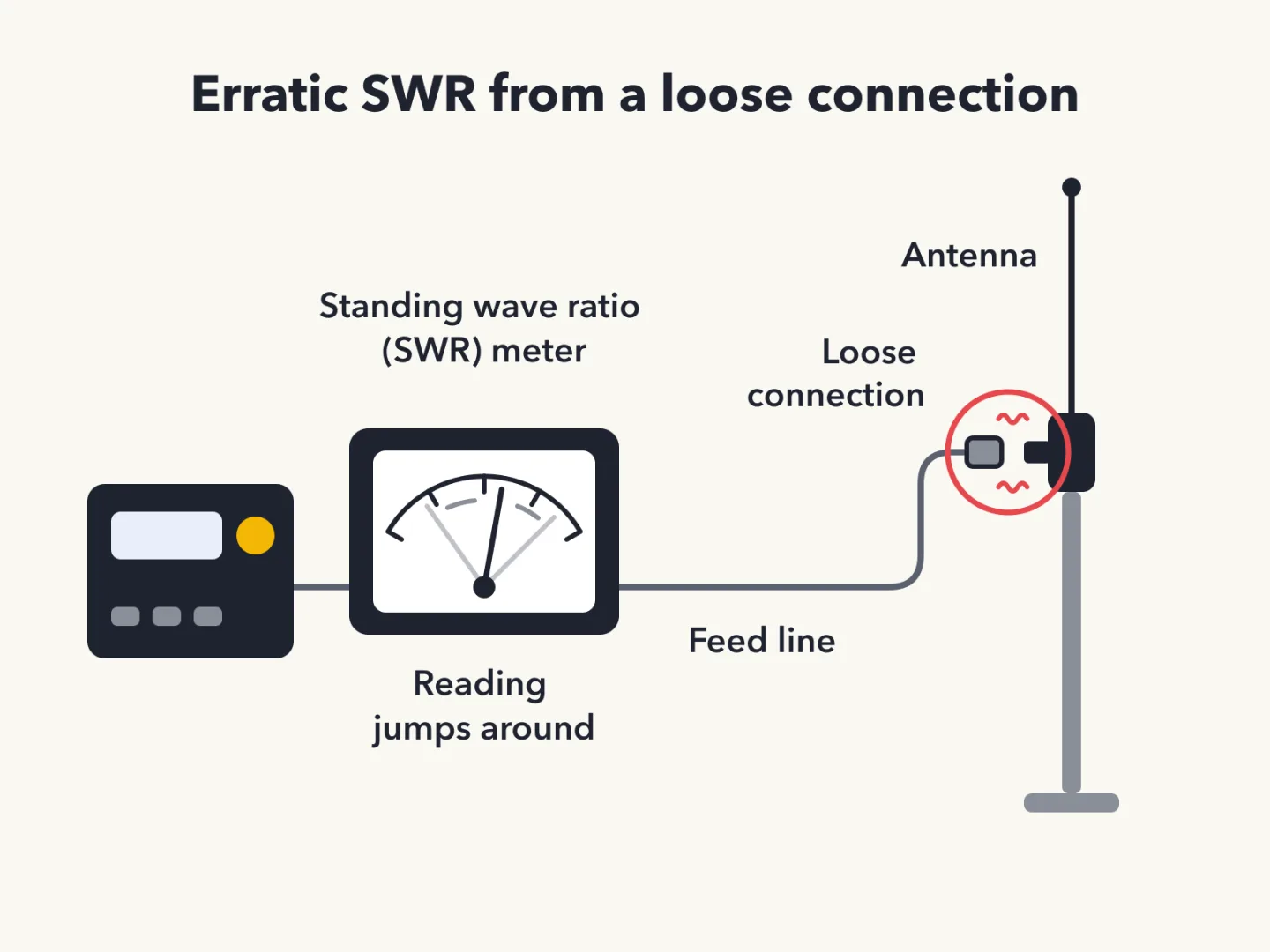
What makes SWR erratic
A loose connection in the antenna or feed line can cause erratic changes in standing wave ratio (SWR).
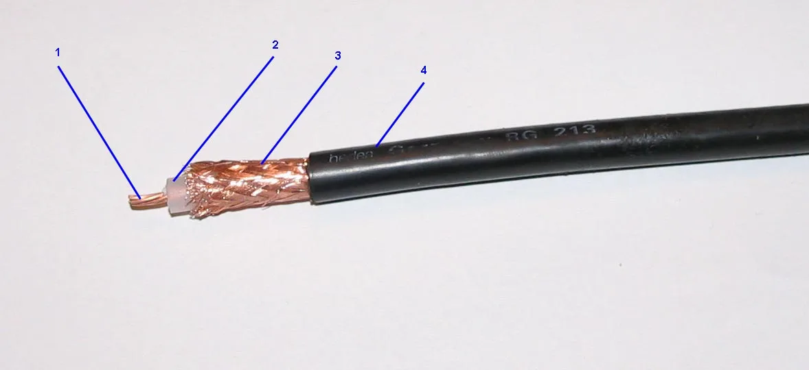
RG-213 versus RG-58
RG-213 cable has less loss at a given frequency than RG-58.
Hardline has the lowest loss
Among 50-ohm flexible coax, multi-conductor unbalanced cable, 75-ohm flexible coax and air-insulated hardline, the hardline has the lowest loss.
Matched pairs
Each item on the left goes with the one on the right.
- Antenna gain
- Signal increase vs a reference antenna
- Type N connector
- Suits frequencies above 400 megahertz
Self-test
Answer each question from memory, then check your work against the answer key.
1. What is a beam antenna?
- AAn antenna built from square aluminum beams
- BAn omnidirectional antenna invented by Clarence Beam
- CAn antenna that focuses the signal into two intense rays
- DAn antenna that concentrates signals in one direction
2. Which of the following types of antennas offers the greatest gain?
- A5/8 wave vertical
- BIsotropic
- CYagi
- DJ pole
3. What is antenna gain?
- AThe additional power that is added to the transmitter power
- BThe increase in signal strength in a specified direction compared to a reference antenna
- CThe increase in impedance on receive or transmit compared to a reference antenna
- DThe additional power the antenna needs on a higher frequency
4. Which of the following describes a type of antenna loading?
- AElectrically lengthening by inserting inductors in radiating elements
- BStrengthening the radiating elements of a beam antenna to better resist wind damage
- CInstalling a spring in the base of a mobile vertical antenna to make it more flexible
- DInserting a resistor in the radiating portion of the antenna to make it resonant
5. How is the polarization of an antenna described?
- ABy the direction of radiation
- BBy the orientation of the electric field
- CBy the shape of the driven element
- DBy the orientation of the magnetic field
6. Which of the following increases the resonant frequency of a dipole antenna?
- AShortening it
- BInserting coils in series with radiating wires
- CAdding capacitive loading to the ends of the radiating wires
- DLengthening it
7. Why is a 19-inch-long vertical antenna often used on 2 meters?
- AIt has low RF radiation exposure
- BIt has high gain
- CIt is a resonant quarter-wave
- DIt is a resonant half-wave
8. What is a disadvantage of a handheld radio transceiver’s short flexible antenna compared to a full-sized quarter-wave antenna?
- AIt only works on analog signals, not digital ones
- BIt transmits only circularly polarized signals
- CIt is more susceptible to receiver desensitization
- DIt has low efficiency
9. What is a potential drawback of using a handheld VHF transceiver inside a vehicle that lacks an externally mounted antenna?
- AThe SWR might decrease, decreasing the signal strength
- BSignal strength is reduced due to the shielding effect of the vehicle
- CThe bandwidth of the antenna will decrease, increasing SWR
- DThe handheld will overheat due to reflected power in the vehicle
10. What is an advantage of a 5/8-wavelength whip antenna for VHF or UHF mobile service compared to a 1/4-wave antenna?
- AIt has lower SWR
- BIt radiates at a higher angle
- CIt has lower impedance
- DIt has more gain
11. In which direction does a half-wave dipole antenna radiate the strongest signal?
- ABroadside to the antenna
- BEqually in all directions
- CIn the direction of the feed line
- DOff the ends of the antenna
12. What is the most common impedance of coaxial cables used in amateur radio?
- A8 ohms
- B600 ohms
- C50 ohms
- D12 ohms
13. Why is coaxial cable the most common feed line for amateur radio antenna systems?
- AIt can handle more power than any other type of feed line
- BIt is less expensive than any other type of feed line
- CIt is easy to use and requires few special installation considerations
- DIt has less loss than any other type of feed line
14. Which of the following connectors should be carefully taped for weather protection when used outdoors?
- AAll these choices are correct
- BBNC
- CPL259
- DType N
15. Which of the following connector types is most suitable as an RF connector for frequencies above 400 MHz?
- APL-259
- BDB-25
- CRS-213
- DType N
16. Which of the following is true of PL-259 type coax connectors?
- AThey are watertight
- BThey are commonly used at HF and VHF frequencies
- CThey are preferred for microwave operation
- DThey are a bayonet-type connector
17. What is the electrical difference between RG-58 and RG-213 coaxial cable?
- ARG-213 cable has less loss at a given frequency
- BRG-58 cable can handle higher power levels
- CThere is no significant difference between the two types
- DRG-58 cable has two shields
18. Which of the following types of feed line has the lowest loss?
- A50-ohm flexible coax
- BAir-insulated hardline
- C75-ohm flexible coax
- DMulti-conductor unbalanced cable
19. What is the major function of an antenna tuner (antenna coupler)?
- AIt automatically selects the proper antenna for the frequency band being used
- BIt allows an antenna to be used on both transmit and receive
- CIt matches the antenna system impedance to the transceiver's output impedance
- DIt helps a receiver automatically tune in weak stations
20. What is standing wave ratio (SWR)?
- AThe transmitter efficiency ratio
- BAn indication of the quality of your station’s ground connection
- CThe ratio of amplifier power output to input
- DA measure of how well a load is matched to a transmission line
21. What happens as the frequency of a signal in coaxial cable is increased?
- AThe characteristic impedance decreases
- BThe characteristic impedance increases
- CThe loss increases
- DThe loss decreases
22. Which of the following is a source of loss in coaxial feed line?
- AWater intrusion into coaxial connectors
- BAll these choices are correct
- CHigh SWR
- DMultiple connectors in the line
23. What can cause erratic changes in SWR?
- ALoose connection in the antenna or feed line
- BLocal thunderstorm
- COverload from a strong local station
- DOver-modulation
Go deeper
- ListenLesson 14 episode
- WatchA 19-Inch Antenna on 2 Meters A 19-inch vertical antenna is often used on 2 meters. Why does such a short antenna work?
- WatchWhen Your Standing Wave Ratio Jumps Around Your standing wave ratio, usually called S-W-R, keeps jumping around.
- StudyHam Radio Technician License in the FlashFeed app
Answer key
- 1. D An antenna that concentrates signals in one directionA beam antenna concentrates signals in one direction. It is not omnidirectional and does not make two intense rays.
- 2. C YagiOf a 5/8 wave vertical, isotropic, J pole and Yagi, the Yagi offers the greatest gain.
- 3. B The increase in signal strength in a specified direction compared to a reference antennaGain is the increase in signal strength in a specified direction compared to a reference antenna. It adds no transmitter power.
- 4. A Electrically lengthening by inserting inductors in radiating elementsLoading electrically lengthens an antenna by inserting inductors in its radiating elements. Resistors, springs and stronger elements are not loading.
- 5. B By the orientation of the electric fieldPolarization is described by the orientation of the electric field, not the magnetic field or direction of radiation.
- 6. A Shortening itShortening a dipole raises its resonant frequency. Lengthening, coils and end capacitive loading do not raise it.
- 7. C It is a resonant quarter-waveA 19-inch vertical is a resonant quarter-wave on 2 meters, not a half-wave or a high-gain antenna. RF stands for radio frequency.
- 8. D It has low efficiencyA short flexible handheld antenna has low efficiency compared with a full-sized quarter-wave antenna.
- 9. B Signal strength is reduced due to the shielding effect of the vehicleInside a vehicle without an outside antenna, signal strength is reduced by the vehicle's shielding effect. VHF stands for very high frequency and SWR stands for standing wave ratio.
- 10. D It has more gainA 5/8-wavelength whip has more gain than a 1/4-wave antenna, not lower standing wave ratio (SWR) or impedance. VHF stands for very high frequency and UHF stands for ultra high frequency.
- 11. A Broadside to the antennaA half-wave dipole radiates its strongest signal broadside, not off the ends or along the feed line.
- 12. C 50 ohmsThe most common impedance of amateur coax is 50 ohms, not 8, 12 or 600.
- 13. C It is easy to use and requires few special installation considerationsCoax is common because it is easy to use and needs few special installation considerations, not because it beats all others in loss, power or cost.
- 14. A All these choices are correctPL259, BNC (usually expanded as Bayonet Neill-Concelman) and Type N connectors should all be carefully taped for weather protection outdoors, so each choice is right.
- 15. D Type NAbove 400 MHz, the most suitable listed connector is the Type N. RF stands for radio frequency.
- 16. B They are commonly used at HF and VHF frequenciesThe PL-259 is commonly used at high frequency (HF) and very high frequency (VHF). It is not for microwave, not watertight and not bayonet-type.
- 17. A RG-213 cable has less loss at a given frequencyRG-213 has less loss at a given frequency than RG-58. RG-58 has no second shield and does not handle more power.
- 18. B Air-insulated hardlineAir-insulated hardline has the lowest loss of the listed feed lines.
- 19. C It matches the antenna system impedance to the transceiver's output impedanceAn antenna tuner matches the antenna system impedance to the transceiver's output impedance.
- 20. D A measure of how well a load is matched to a transmission lineSWR measures how well a load is matched to a transmission line, not power ratio, efficiency or ground quality.
- 21. C The loss increasesCoax loss increases as signal frequency increases.
- 22. B All these choices are correctWater in connectors, high standing wave ratio (SWR) and multiple connectors are each sources of loss, so all choices are correct.
- 23. A Loose connection in the antenna or feed lineA loose connection in the antenna or feed line can cause erratic standing wave ratio (SWR). Storms, over-modulation and overload do not.
Sources
- NCVEC Question Pool Committee — 2026–2030 Technician question pool — ncvec.org/index.php/2026-2030-technician-question-pool
Image credits
- What a beam antenna does: Wikimedia Commons · UnifiedFunctionality · CC BY-SA 3.0 — commons.wikimedia.org/wiki/File:Yagi_aerial_antenna_above_trees.jpg
- Antenna gain defined: FlashFeed original diagram · CC-BY-4.0
- The Yagi has the most gain: Wikimedia Commons · Adityamadhav83 · CC BY-SA 4.0 — commons.wikimedia.org/wiki/File:A_television_antenna_in_Kakinada.JPG
- How polarization is described: FlashFeed original diagram · CC-BY-4.0
- Antenna loading explained: FlashFeed original diagram · CC-BY-4.0
- Shorter dipole, higher frequency: FlashFeed original diagram · CC-BY-4.0
- The 19-inch 2-meter vertical: FlashFeed original diagram · CC-BY-4.0
- The handheld's short antenna: Wikimedia Commons · Jakez · CC BY-SA 3.0 — commons.wikimedia.org/wiki/File:ICOM_IC-T3H.JPG
- Handheld inside a vehicle: FlashFeed original diagram · CC-BY-4.0
- Why a 5/8-wavelength whip: FlashFeed original diagram · CC-BY-4.0
- Where a dipole radiates most: FlashFeed original diagram · CC-BY-4.0
- Taping connectors outdoors: FlashFeed original diagram · CC-BY-4.0
- Common coax impedance: Wikimedia Commons · Wtshymanski · CC BY-SA 4.0 — commons.wikimedia.org/wiki/File:Coaxial_cable_braided_wire.jpg
- What an antenna tuner does: FlashFeed original diagram · CC-BY-4.0
- Coax loss rises with frequency: FlashFeed original diagram · CC-BY-4.0
- Type N above 400 megahertz: Wikimedia Commons · Swift.Hg · CC BY-SA 3.0 — commons.wikimedia.org/wiki/File:Male_type_N_connector.jpg
- Where the PL-259 is used: Wikimedia Commons · Appaloosa · CC BY-SA 3.0 — commons.wikimedia.org/wiki/File:UHF_PL_Connector.jpg
- Sources of loss in coax: FlashFeed original diagram · CC-BY-4.0
- What makes SWR erratic: FlashFeed original diagram · CC-BY-4.0
- RG-213 versus RG-58: Wikimedia Commons · User Appaloosa on de.wikipedia · CC BY-SA 3.0 — commons.wikimedia.org/wiki/File:Rg213_1.jpg


