
Ham Radio Technician License study guide · Lesson 9 of 15
Electronic Components: Schematics and Circuits
Schematic diagrams and symbols · Component functions and resonant circuits
This is the lesson's study guide from the FlashFeed app, plus its key facts and a self-test.
What you'll be able to do
- Identify a schematic and the basic parts shown in a simple circuit diagram, such as resistors, transistors, lamps and batteries
- Identify the symbols for capacitors, inductors, LEDs, transformers, variable parts and antennas on a schematic
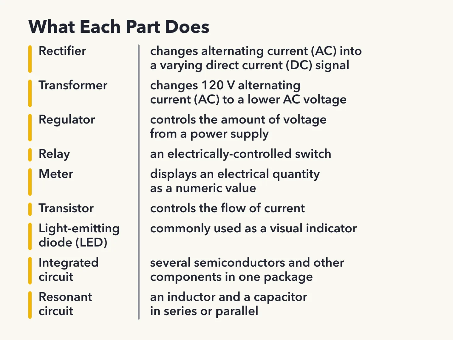
- Explain what rectifiers, relays, regulators, transformers, transistors and meters do in a circuit
- Describe resonant circuits, shielded wire, LED indicators and integrated circuits and what each is used for
Radio circuits are drawn as diagrams, and a new licensee needs to read them. This lesson covers what a schematic is, how the common parts are labeled in the sample diagrams, and what several key parts do. It also covers resonant circuits and shielded wire. Knowing the parts by name and by job makes any radio diagram easier to follow.
Schematic diagrams and symbols
An electrical diagram that uses standard component symbols is called a schematic. Each part in a schematic is drawn with its own agreed symbol, so a reader who knows the symbols can tell the parts apart on the page.
What a schematic shows
A schematic accurately represents the component connections. It shows which part is joined to which, and that is the information a circuit diagram exists to give.
In practice, a part that looks big and bulky in real life may be a small symbol on the page. A long wire may be a short line. Only the connections between the symbols can be trusted.
The first sample diagram
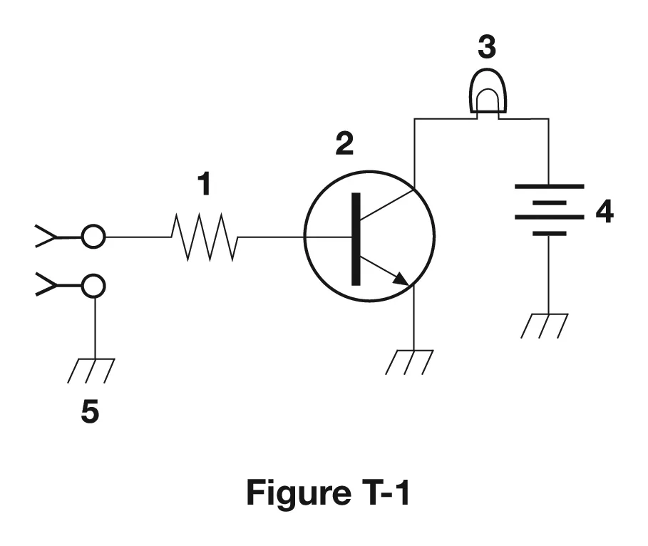
Figure T-1 is a simple circuit whose parts are numbered. Each number points to one symbol.
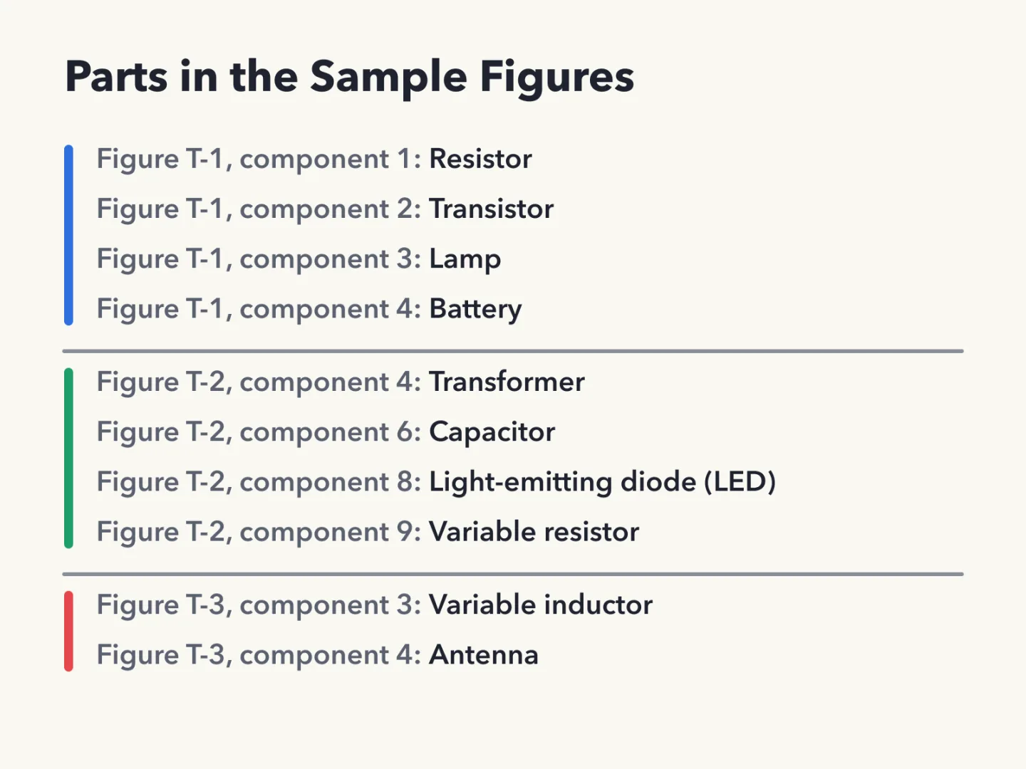
- Component 1 is a resistor.
- Component 2 is a transistor.
- Component 3 is a lamp.
- Component 4 is a battery.
In this figure, the resistor and the transistor are separate symbols with separate jobs, and the lamp and the battery are distinct as well.
The second sample diagram
Figure T-2 is a second circuit diagram. Its numbers are separate from those in figure T-1, so the same number means a different part here.
- Component 4 is a transformer.
- Component 6 is a capacitor.
- Component 8 is a light emitting diode (LED).
- Component 9 is a variable resistor.
The third sample diagram
Figure T-3 adds two more symbols. Component 3 is a variable inductor. Component 4 is an antenna.
Component 4 appears in all three figures, and it is a different part each time. In figure T-1 it is the battery, in figure T-2 the transformer, and in figure T-3 the antenna. Numbers only have meaning inside their own diagram.
Sources
Component functions and resonant circuits
Knowing a symbol is half the job. The other half is knowing what the part does in a circuit. These are the functions a Technician licensee should connect to each part.
Changing power
A rectifier is the device or circuit that changes an alternating current (AC) into a varying direct current (DC) signal.
A transformer is the component that changes 120 V AC power to a lower AC voltage for other uses. Both of these parts work on alternating current, but they do different jobs. The transformer changes the AC voltage and the output is still AC. The rectifier changes AC into varying DC.
A regulator is the type of circuit that controls the amount of voltage from a power supply. A small power supply can draw on all three parts: a transformer to lower the AC voltage, a rectifier to change AC to varying DC, and a regulator to control the voltage the supply delivers.
Switching, controlling and measuring
A relay is an electrically-controlled switch.
A transistor controls the flow of current. This is the function of component 2 in figure T-1.
A meter displays an electrical quantity as a numeric value.
Indicators and integrated circuits
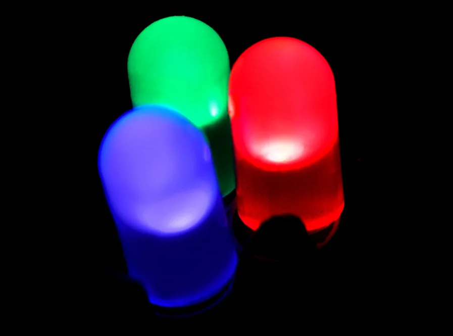
An LED is the part commonly used as a visual indicator.
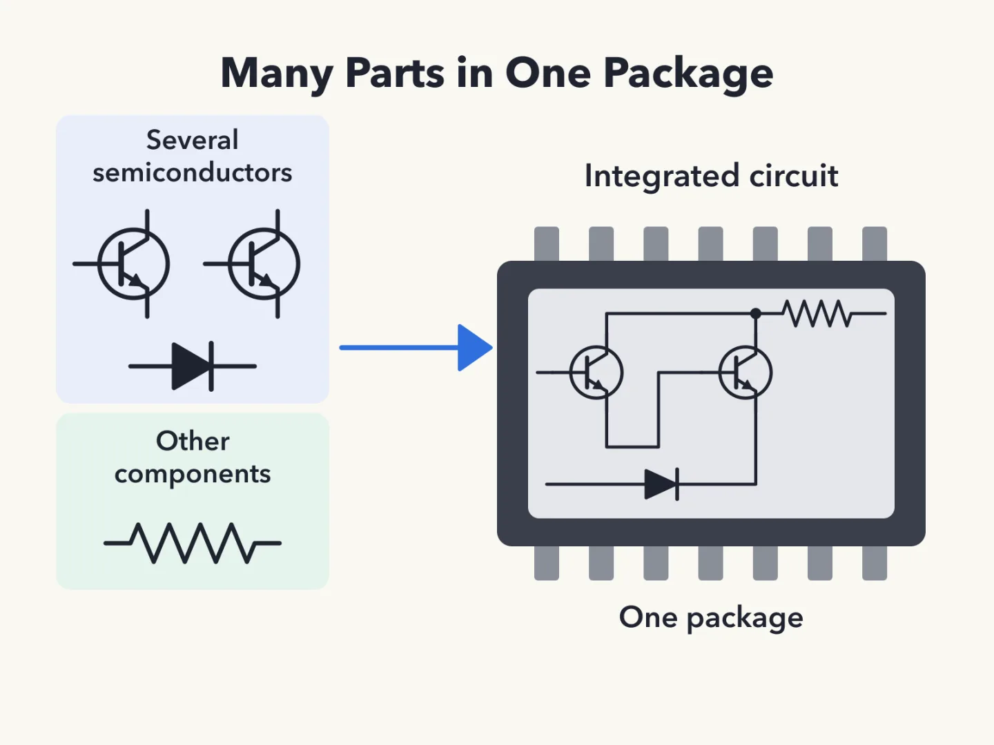
An integrated circuit is a device that combines several semiconductors and other components into one package.
Tuned circuits and shielded wire
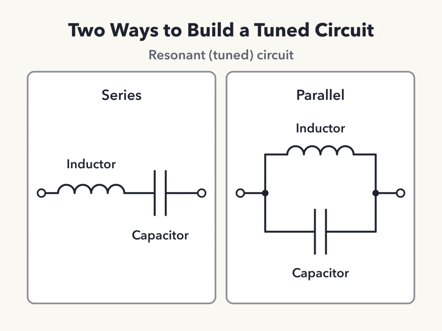
A resonant circuit, also called a tuned circuit, is made from an inductor and a capacitor in series or parallel. A capacitor is therefore the part combined with an inductor to make a resonant circuit.
Shielded wire is used to prevent coupling of unwanted signals to or from the wire. That is its reason for use. Shielding works in both directions: it keeps unwanted signals from getting into the wire and from getting out of it.
Sources
Key facts
What a Schematic Is
An electrical diagram that uses standard component symbols is called a schematic. Each part is drawn with its own agreed symbol.
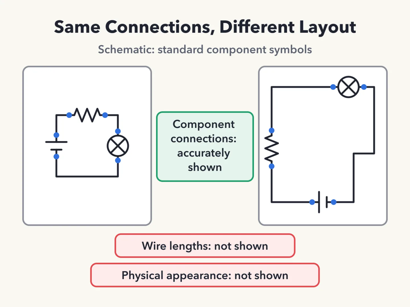
What a Schematic Shows
A schematic accurately represents the component connections. Only the connections between the symbols can be trusted.
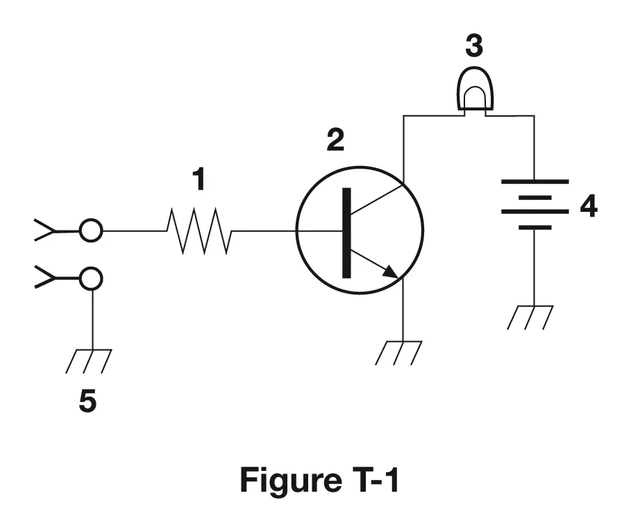
Component 1 in Figure T-1
Figure T-1 is a simple circuit whose parts are numbered. Component 1 is a resistor.
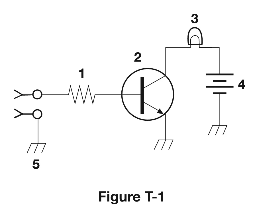
Component 2 in Figure T-1
In figure T-1, component 2 is a transistor. The resistor and the transistor are separate symbols with separate jobs.
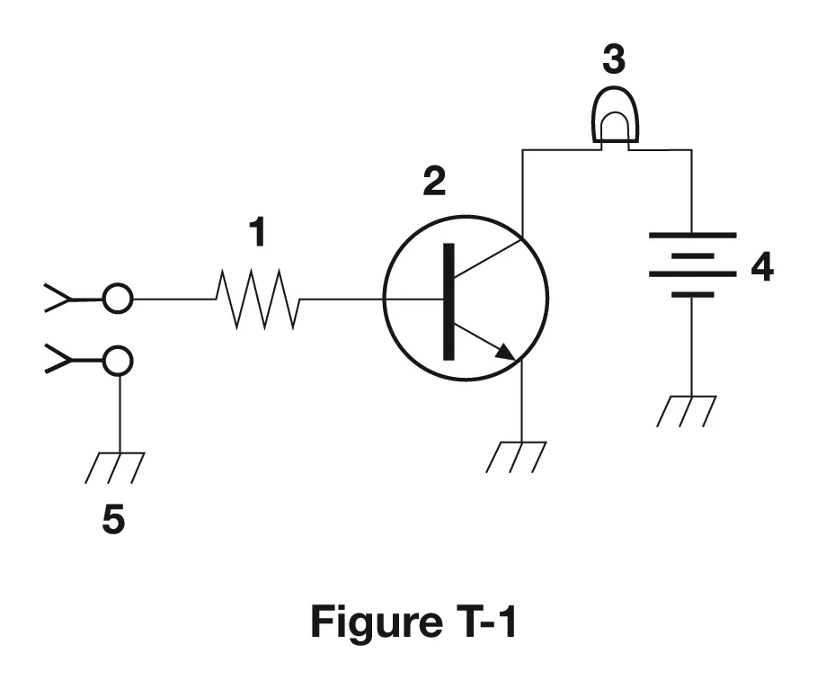
Component 3 in Figure T-1
In figure T-1, component 3 is a lamp.
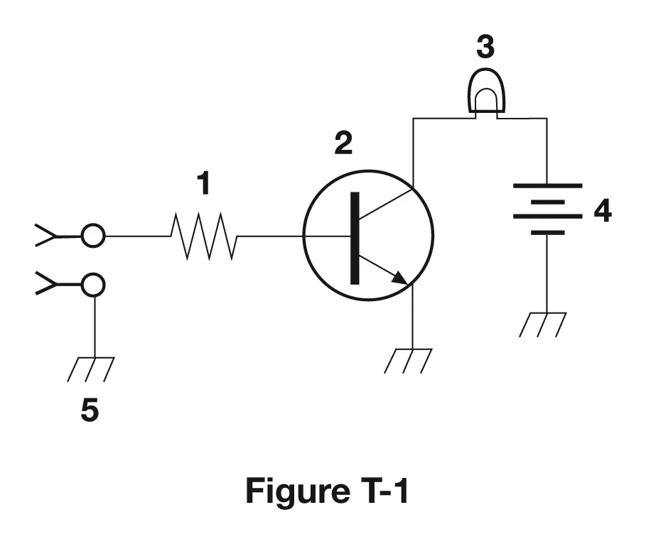
Component 4 in Figure T-1
In figure T-1, component 4 is a battery.
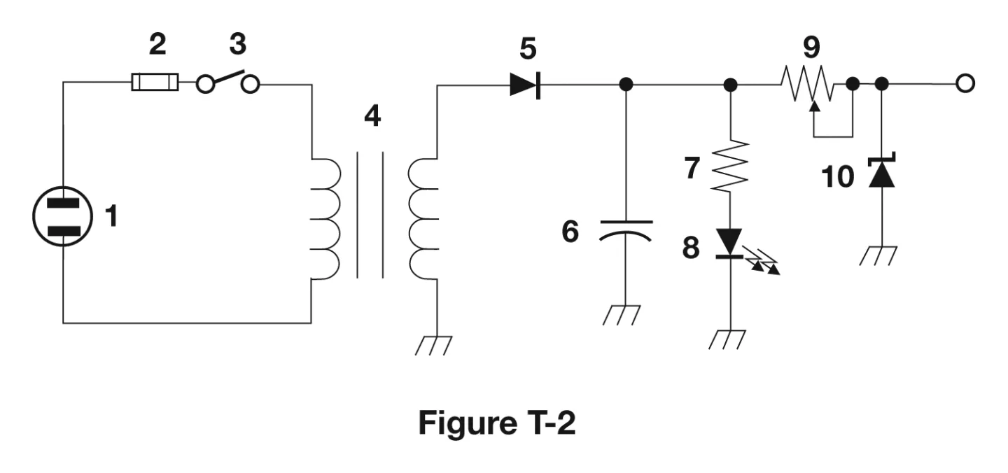
Component 6 in Figure T-2
Figure T-2 numbers its parts separately from figure T-1. In figure T-2, component 6 is a capacitor.
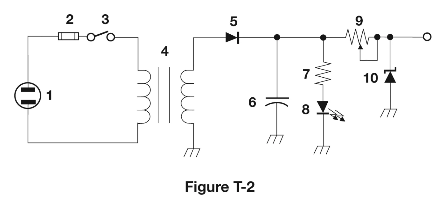
Component 8 in Figure T-2
In figure T-2, component 8 is a light emitting diode (LED).
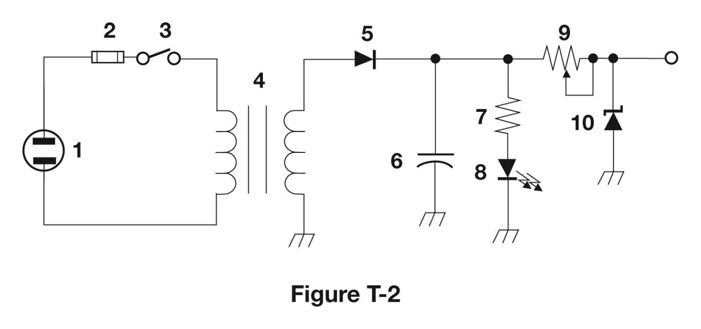
Component 9 in Figure T-2
In figure T-2, component 9 is a variable resistor.
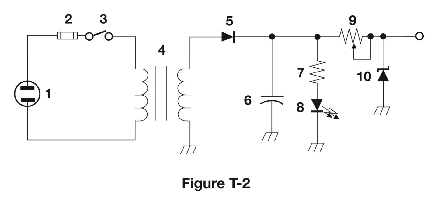
Component 4 in Figure T-2
In figure T-2, component 4 is a transformer.
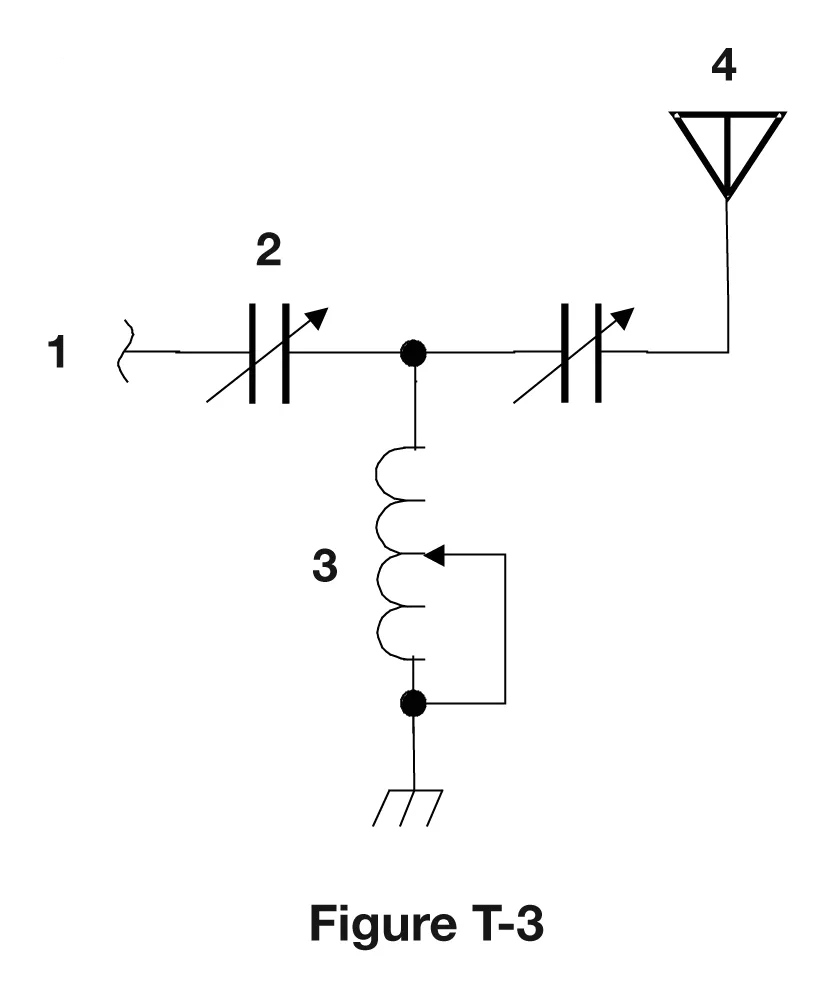
Component 3 in Figure T-3
In figure T-3, component 3 is a variable inductor.
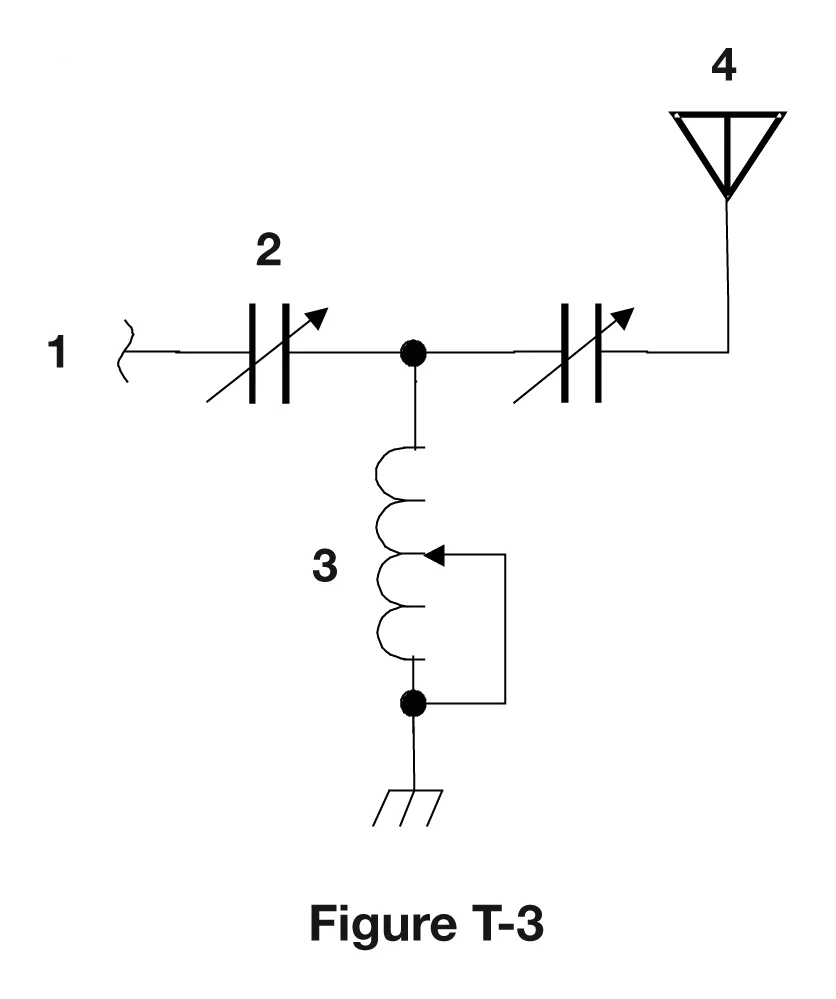
Component 4 in Figure T-3
In figure T-3, component 4 is an antenna. Component 4 is a different part in each of the three figures, so numbers only have meaning inside their own diagram.
Rectifier Changes AC to DC
A rectifier changes alternating current (AC) into a varying direct current (DC) signal.
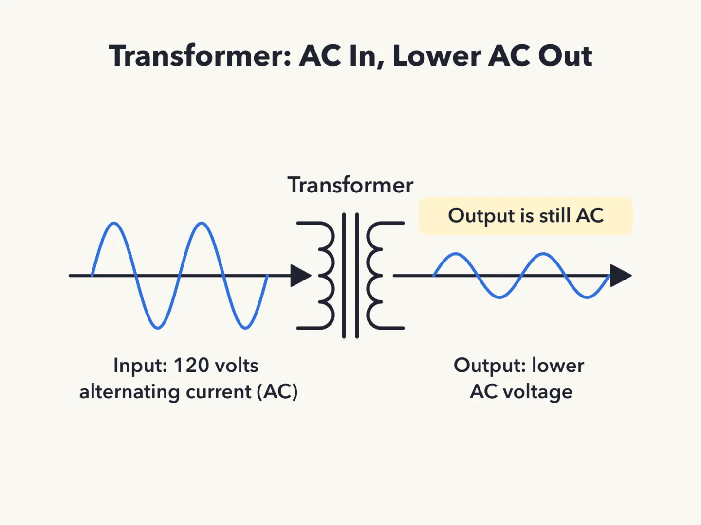
Transformer Lowers AC Voltage
A transformer changes 120 V alternating current (AC) to a lower AC voltage for other uses. The output is still AC.
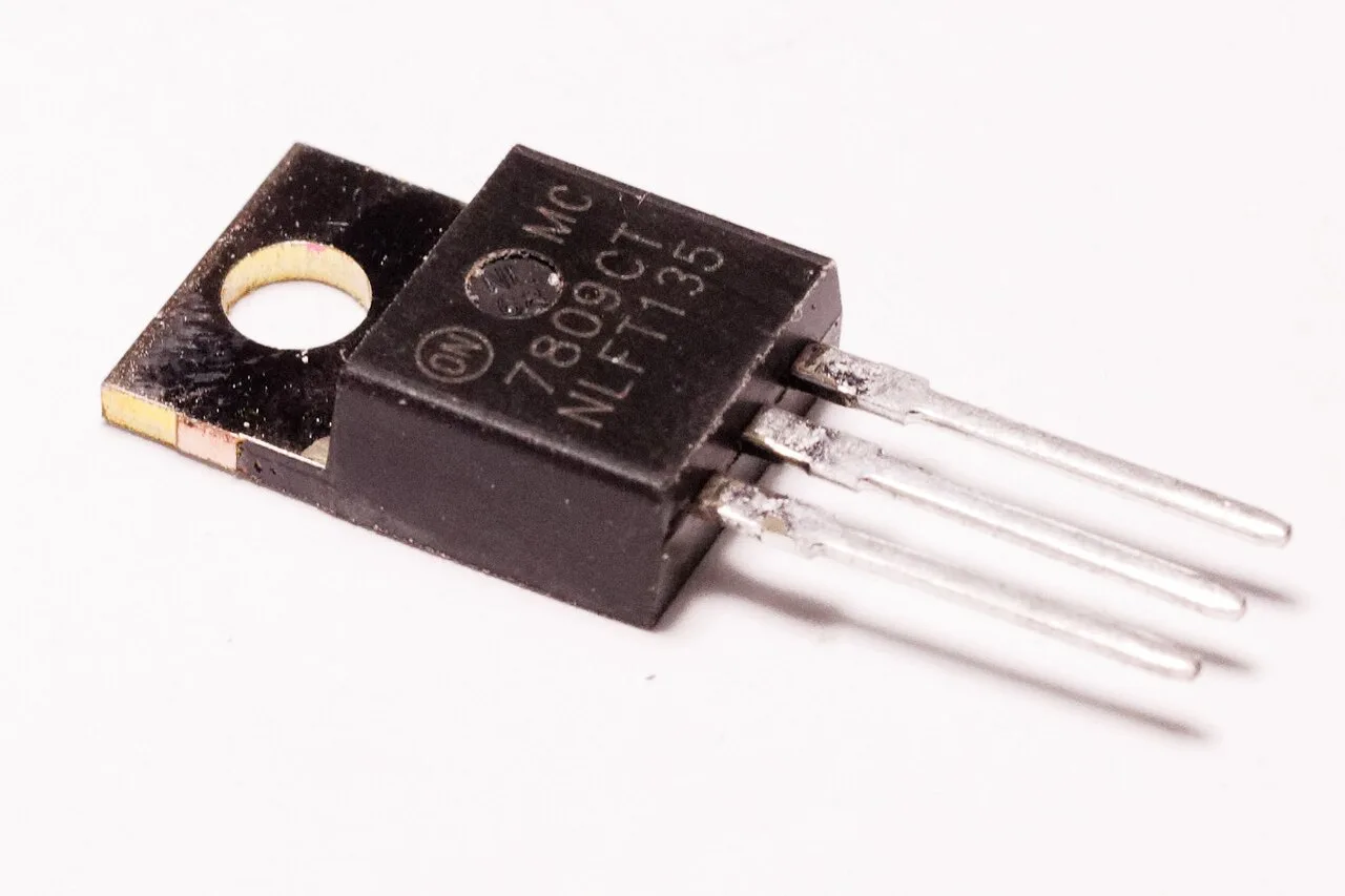
Regulator Controls Voltage
A regulator is the type of circuit that controls the amount of voltage from a power supply.
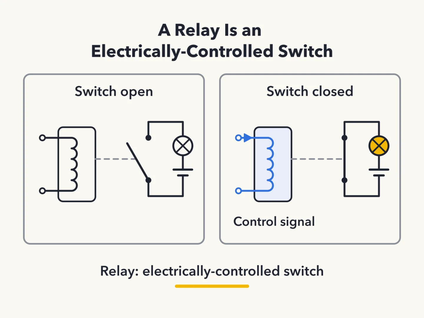
A Relay Is a Switch
A relay is an electrically-controlled switch.
Function of a Transistor
A transistor controls the flow of current. That is the function of component 2 in figure T-1.
A Meter Shows a Number
A meter displays an electrical quantity as a numeric value.
LED as Visual Indicator
A light-emitting diode (LED) is the part commonly used as a visual indicator.
Integrated Circuit Defined
An integrated circuit is a device that combines several semiconductors and other components into one package.
Capacitor Pairs With Inductor
A capacitor is the part combined with an inductor to make a resonant circuit.
What a Resonant Circuit Is
A resonant circuit, also called a tuned circuit, is made from an inductor and a capacitor in series or parallel.
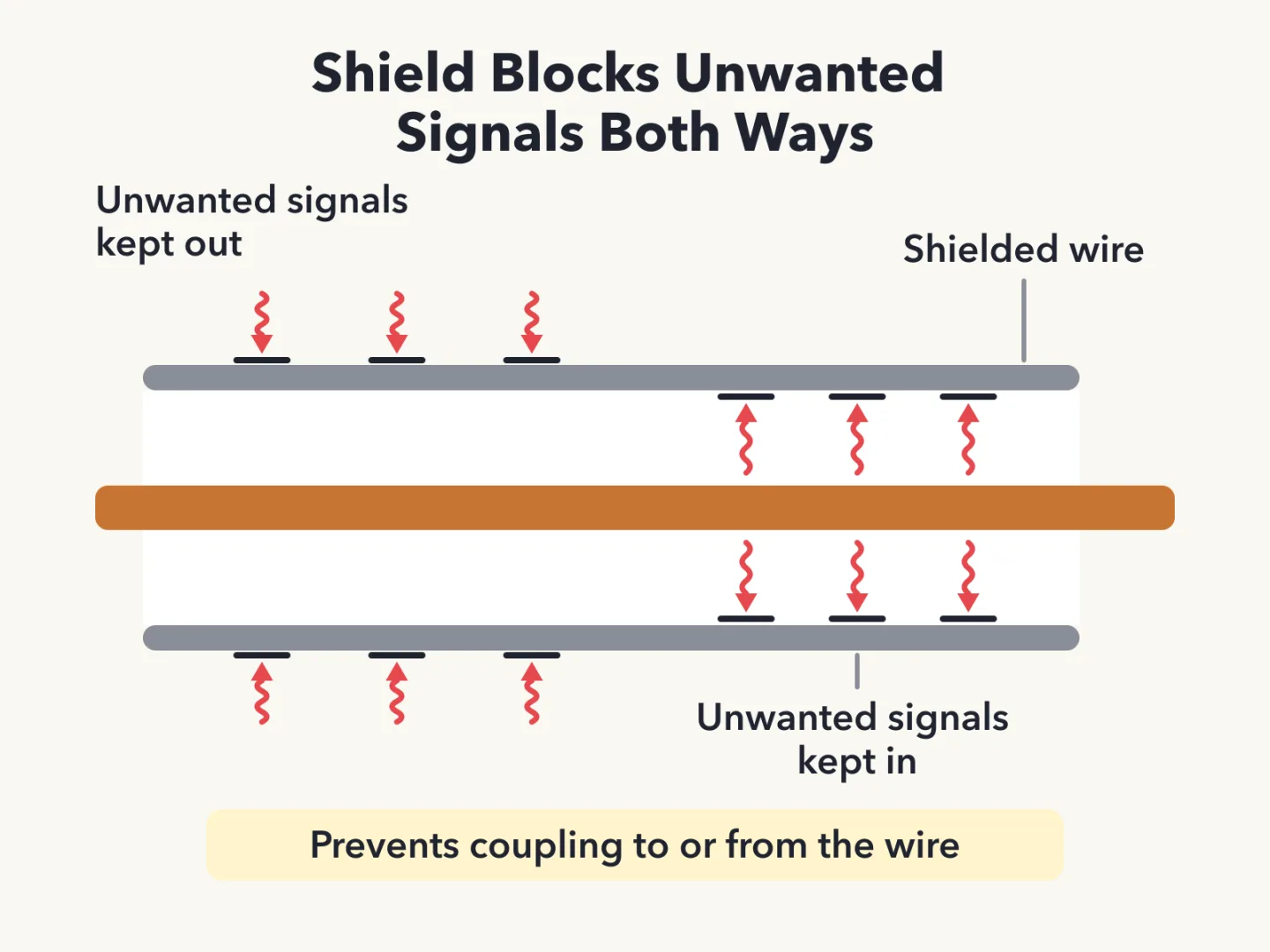
Why Use Shielded Wire
Shielded wire is used to prevent coupling of unwanted signals to or from the wire.
Matched pairs
Each item on the left goes with the one on the right.
- Integrated circuit
- Many parts in one package
Self-test
Answer each question from memory, then check your work against the answer key.
1. What is an electrical diagram using standard component symbols called?
- AInstrumentation system
- BFlow chart
- CConnection chart
- DSchematic
2. Which of the following is accurately represented in electrical schematics?
- AComponent connections
- BAll these choices are correct
- CPhysical appearance of components
- DWire lengths
3. What is component 1 in figure T-1?
- ATransistor
- BResistor
- CBattery
- DConnector
4. What is component 2 in figure T-1?
- AResistor
- BIndicator lamp
- CTransistor
- DConnector
5. What is component 3 in figure T-1?
- AResistor
- BLamp
- CGround symbol
- DTransistor
6. What is component 4 in figure T-1?
- AResistor
- BTransistor
- CBattery
- DGround symbol
7. What is component 6 in figure T-2?
- ACapacitor
- BRegulator IC
- CTransistor
- DResistor
8. What is component 8 in figure T-2?
- AInductor
- BResistor
- CRegulator IC
- DLight emitting diode
9. What is component 9 in figure T-2?
- AVariable resistor
- BVariable inductor
- CVariable capacitor
- DVariable transformer
10. What is component 4 in figure T-2?
- AVariable inductor
- BDouble-pole switch
- CTransformer
- DPotentiometer
11. What is component 3 in figure T-3?
- AVariable capacitor
- BConnector
- CMeter
- DVariable inductor
12. What is component 4 in figure T-3?
- AGround
- BAntenna
- CDummy load
- DTransmitter
13. Which of the following devices or circuits changes an alternating current into a varying direct current signal?
- AReflector
- BTransformer
- CAmplifier
- DRectifier
14. What component changes 120 V AC power to a lower AC voltage for other uses?
- ATransformer
- BVariable capacitor
- CTransistor
- DDiode
15. What is a relay?
- AA current-controlled amplifier
- BAn electrically-controlled switch
- CAn inverting amplifier
- DA pass transistor
16. What type of circuit controls the amount of voltage from a power supply?
- AOscillator
- BPhase inverter
- CRegulator
- DFilter
17. Which of the following displays an electrical quantity as a numeric value?
- APotentiometer
- BMeter
- CRelay
- DTransistor
18. What is the function of component 2 in figure T-1?
- AControl the flow of current
- BConvert electrical energy into radio waves
- CSupply electrical energy
- DGive off light when current flows through it
19. Which of the following is combined with an inductor to make a resonant circuit?
- AZener diode
- BResistor
- CPotentiometer
- DCapacitor
20. Which of the following is a resonant or tuned circuit?
- AA circuit designed to provide high-fidelity audio
- BA resistor circuit used for reducing standing wave ratio
- CAn inductor and a capacitor in series or parallel
- DA linear voltage regulator
21. Which of the following is a reason to use shielded wire?
- ATo increase the current carrying capability of the wire
- BTo decrease the resistance of DC power connections
- CTo prevent coupling of unwanted signals to or from the wire
- DTo reduce receiver overload
22. Which of the following is commonly used as a visual indicator?
- ALED
- BFET
- CAll these choices are correct
- DZener diode
23. What is the name of a device that combines several semiconductors and other components into one package?
- ATransformer
- BMulti-pole relay
- CTransducer
- DIntegrated circuit
Go deeper
- ListenLesson 9 episode
- WatchWhat a Schematic Leaves Out A circuit diagram can draw a big part as a small symbol, and a long wire as a short line.
- WatchLowering 120 Volts in a Power Supply Which part takes 120 volts of alternating current and lowers its voltage?
- StudyHam Radio Technician License in the FlashFeed app
Answer key
- 1. D SchematicA diagram using standard component symbols is a schematic, not a connection chart, instrumentation system or flow chart.
- 2. A Component connectionsA schematic accurately represents component connections, not wire lengths or physical appearance.
- 3. B ResistorComponent 1 in figure T-1 is a resistor.
- 4. C TransistorComponent 2 in figure T-1 is a transistor.
- 5. B LampComponent 3 in figure T-1 is a lamp.
- 6. C BatteryComponent 4 in figure T-1 is a battery.
- 7. A CapacitorComponent 6 in figure T-2 is a capacitor. IC stands for integrated circuit.
- 8. D Light emitting diodeComponent 8 in figure T-2 is a light emitting diode. IC stands for integrated circuit.
- 9. A Variable resistorComponent 9 in figure T-2 is a variable resistor.
- 10. C TransformerComponent 4 in figure T-2 is a transformer.
- 11. D Variable inductorComponent 3 in figure T-3 is a variable inductor.
- 12. B AntennaComponent 4 in figure T-3 is an antenna.
- 13. D RectifierA rectifier changes alternating current (AC) into varying direct current (DC); a transformer only changes the AC voltage.
- 14. A TransformerA transformer changes 120 V alternating current (AC) to a lower AC voltage.
- 15. B An electrically-controlled switchA relay is an electrically-controlled switch, not an amplifier or pass transistor.
- 16. C RegulatorA regulator controls the amount of voltage from a power supply.
- 17. B MeterA meter displays an electrical quantity as a numeric value.
- 18. A Control the flow of currentA transistor controls the flow of current; it does not light up, supply energy or make radio waves.
- 19. D CapacitorA capacitor is combined with an inductor to make a resonant circuit.
- 20. C An inductor and a capacitor in series or parallelA tuned circuit is an inductor and a capacitor in series or parallel.
- 21. C To prevent coupling of unwanted signals to or from the wireShielded wire prevents coupling of unwanted signals to or from the wire. DC stands for direct current.
- 22. A LEDA light-emitting diode (LED) is commonly used as a visual indicator; a field effect transistor (FET) and a Zener diode are not, so "all correct" is wrong.
- 23. D Integrated circuitAn integrated circuit combines several semiconductors and other components into one package.
Sources
- NCVEC Question Pool Committee — 2026–2030 Technician question pool — ncvec.org/index.php/2026-2030-technician-question-pool
Image credits
- What a Schematic Is: FlashFeed original diagram · CC-BY-4.0
- What a Schematic Shows: FlashFeed original diagram · CC-BY-4.0
- Component 1 in Figure T-1: NCVEC Question Pool Committee · Public domain — ncvec.org/index.php/2026-2030-technician-question-pool
- Component 2 in Figure T-1: NCVEC Question Pool Committee · Public domain — ncvec.org/index.php/2026-2030-technician-question-pool
- Component 3 in Figure T-1: NCVEC Question Pool Committee · Public domain — ncvec.org/index.php/2026-2030-technician-question-pool
- Component 4 in Figure T-1: NCVEC Question Pool Committee · Public domain — ncvec.org/index.php/2026-2030-technician-question-pool
- Component 6 in Figure T-2: NCVEC Question Pool Committee · Public domain — ncvec.org/index.php/2026-2030-technician-question-pool
- Component 8 in Figure T-2: NCVEC Question Pool Committee · Public domain — ncvec.org/index.php/2026-2030-technician-question-pool
- Component 9 in Figure T-2: NCVEC Question Pool Committee · Public domain — ncvec.org/index.php/2026-2030-technician-question-pool
- Component 4 in Figure T-2: NCVEC Question Pool Committee · Public domain — ncvec.org/index.php/2026-2030-technician-question-pool
- Component 3 in Figure T-3: NCVEC Question Pool Committee · Public domain — ncvec.org/index.php/2026-2030-technician-question-pool
- Component 4 in Figure T-3: NCVEC Question Pool Committee · Public domain — ncvec.org/index.php/2026-2030-technician-question-pool
- Rectifier Changes AC to DC: FlashFeed original diagram · CC-BY-4.0
- Transformer Lowers AC Voltage: FlashFeed original diagram · CC-BY-4.0
- Regulator Controls Voltage: Wikimedia Commons · Retired electrician · CC0 — commons.wikimedia.org/wiki/File:7809_(OnSemi)_01.jpg
- A Relay Is a Switch: FlashFeed original diagram · CC-BY-4.0
- Function of a Transistor: NCVEC Question Pool Committee · Public domain — ncvec.org/index.php/2026-2030-technician-question-pool
- LED as Visual Indicator: Wikimedia Commons · PiccoloNamek · CC BY-SA 3.0 — commons.wikimedia.org/wiki/File:RBG-LED.jpg
- Integrated Circuit Defined: FlashFeed original diagram · CC-BY-4.0
- What a Resonant Circuit Is: FlashFeed original diagram · CC-BY-4.0
- Why Use Shielded Wire: FlashFeed original diagram · CC-BY-4.0

