
Ham Radio Technician License study guide · Lesson 10 of 15
Practical Circuits: Radios and Their Common Problems
Station equipment and receiver concepts · Transmitter and receiver problems
This is the lesson's study guide from the FlashFeed app, plus its key facts and a self-test.
What you'll be able to do
- Explain basic receiver and circuit terms: sensitivity, selectivity, mixers, oscillators, VFOs and modulation
- Identify station equipment (transceivers, transverters, amplifiers) and describe what each does and how PTT and mode switches work
- Explain why a station causes interference to broadcast, TV and other receivers and how to reduce it
- Identify causes and cures of over-deviation, distorted audio, RF feedback on a microphone cable, low power from high SWR and interference
This lesson covers the building blocks inside a radio and the equipment around it, such as transceivers, transverters and power amplifiers. It also covers the common ways a station goes wrong. A new licensee needs both: the vocabulary to read a radio's controls and specifications, and a sense of what to check when a signal sounds bad or a neighbor's TV acts up.
Station equipment and receiver concepts
Judging a receiver
Two terms rate how well a receiver performs. Sensitivity is the ability of a receiver to detect the presence of a signal. Selectivity is the ability of a receiver to discriminate between multiple signals, which means picking out one signal from among several. The two are easy to confuse: sensitivity is about detecting a signal at all, while selectivity is about telling signals apart.
Circuit building blocks
A mixer converts a signal from one frequency to another.
An oscillator is a circuit that generates a signal at a specific frequency.
Modulation is combining speech with a radio frequency (RF) carrier signal.
The variable frequency oscillator (VFO) in a transceiver sets the receive and transmit frequency.
Transceivers and add-on equipment
A transceiver is a device that combines a receiver and a transmitter.
A transverter is the device that converts the RF input and output of a transceiver to another band. This is how a transceiver can work on a band it does not cover itself.
Push to talk
A transceiver's push to talk (PTT) input switches the transceiver from receive to transmit when it is grounded.
Raising output power
An RF power amplifier added to the output of a transceiver increases the transmitted output power.
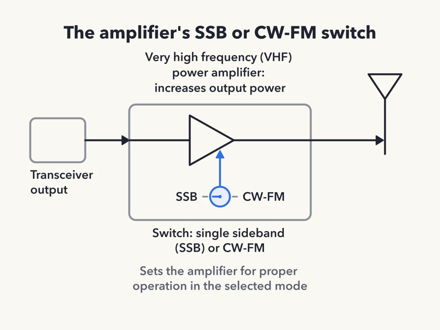
Some very high frequency (VHF) power amplifiers have a switch that selects either single sideband (SSB) or CW-FM, where CW means International Morse code telegraphy and FM stands for frequency modulated. That switch sets the amplifier for proper operation in the selected mode.
How the pieces fit together
Read along a transceiver's signal path and these terms line up. The VFO sets the frequency. Oscillators make signals at specific frequencies, and mixers move signals from one frequency to another. In transmitting, modulation puts speech onto the RF carrier. The PTT input decides whether the radio is receiving or transmitting. An RF power amplifier on the output raises the transmitted power, and a transverter carries the transceiver's input and output to a different band. Sensitivity and selectivity then describe how well the receiving side hears the signal it wants.
Sources
Transmitter and receiver problems
Why other receivers hear a station
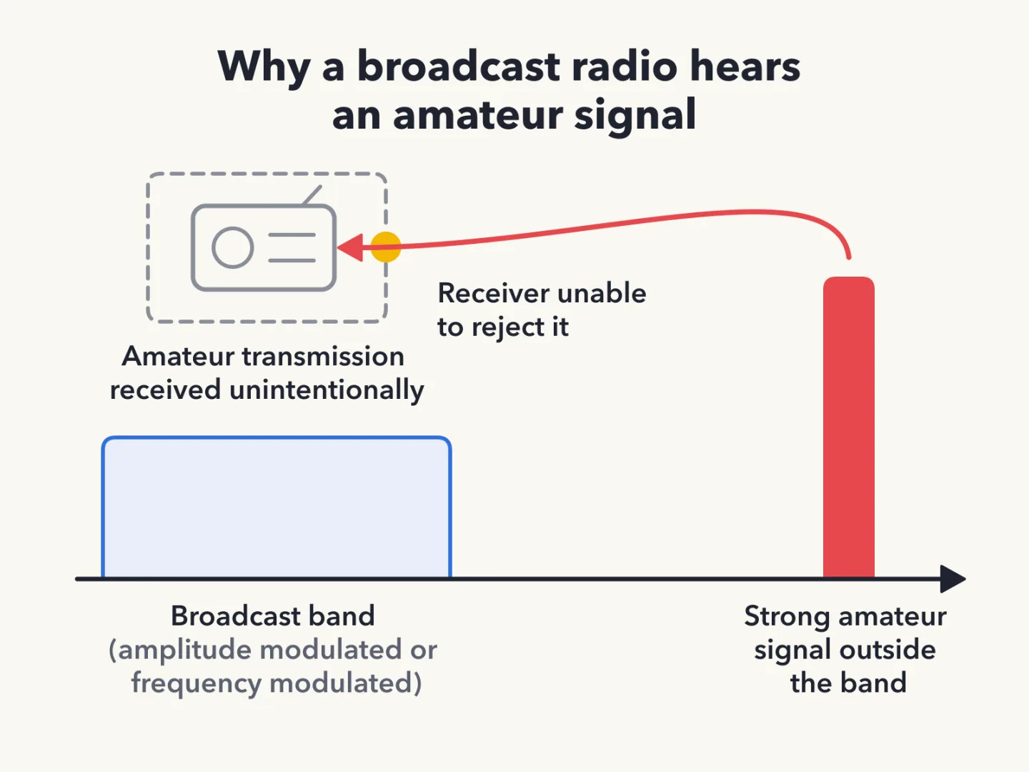
A broadcast amplitude modulated (AM) or FM radio can pick up an amateur transmission unintentionally because the receiver is unable to reject strong signals outside the AM or FM band.
Radio frequency interference can come from several sources. Fundamental overload, harmonics and spurious emissions can each cause it.
Reducing interference at the affected receiver
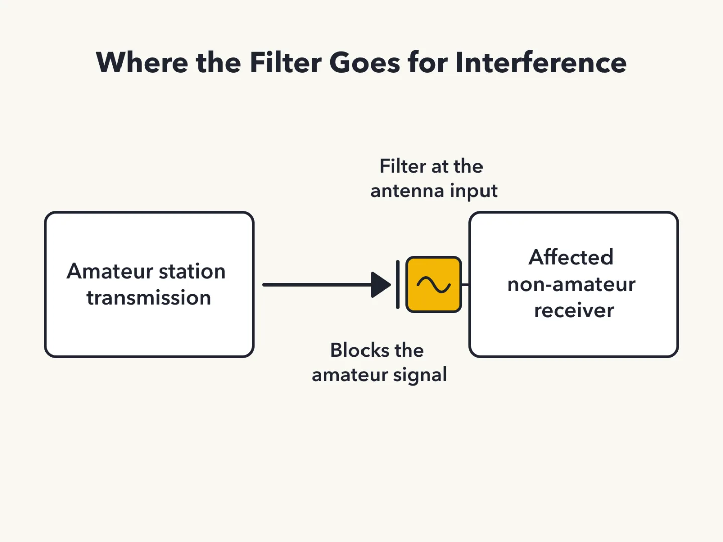
To reduce interference by an amateur station to a non-amateur over-the-air radio receiver, block the amateur signal with a filter at the antenna input of the affected receiver.
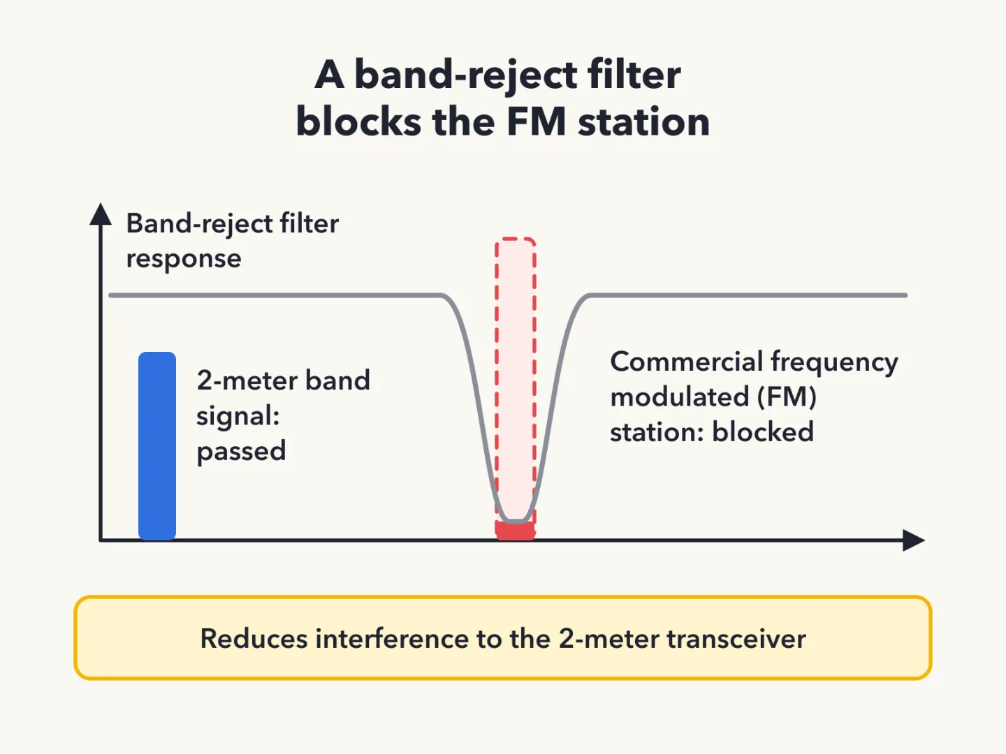
A band-reject filter can reduce interference to a 2-meter band transceiver from a nearby commercial FM station.
For interference to non-fiber optic cable TV, the first step is to be sure all TV feed line coaxial connectors are installed properly.
When a neighbor reports interference
If a neighbor says a station's transmissions are interfering with their radio or TV reception, the operator should first make sure the station is functioning properly. It should not cause interference to the operator's own radio or television when tuned to the same channel.
The problem can also run the other way. Harmful interference is interference that endangers radionavigation or other safety services, or one that "seriously degrades, obstructs or repeatedly interrupts a radiocommunication service operating in accordance with the Radio Regulations." When something in a neighbor's home causes harmful interference to an amateur station, all three of these responses are correct:
- Work with the neighbor to identify the offending device.
- Politely inform the neighbor that Federal Communications Commission (FCC) rules prohibit the use of devices that cause interference.
- Make sure the station meets the standards of good amateur practice.
Distorted audio and low power
A report that an FM handheld or mobile transceiver is over-deviating is answered by talking farther away from the microphone.
A report that audio through an FM repeater is distorted or unintelligible can have several causes. The transmitter may be slightly off frequency. The operator may be speaking too loudly or too close to the microphone. The operator may also be in a bad location. All three are correct.
A clip-on ferrite "choke" on the microphone cable can eliminate distorted voice transmissions. It prevents the transmitted signal from feeding back into the transmitter.
Finally, a high standing wave ratio (SWR) might be the cause of low RF power output from a solid-state transceiver.
Sources
Key terms
- Harmful interference
- Interference that endangers radionavigation or other safety services, or seriously degrades, obstructs or repeatedly interrupts a radiocommunication service operating under the Radio Regulations
Key facts
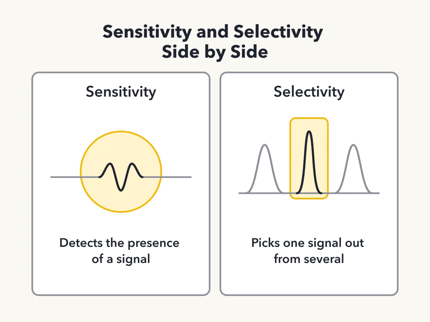
Sensitivity: Detecting a Signal
Sensitivity is the ability of a receiver to detect the presence of a signal.
Selectivity: Telling Signals Apart
Selectivity is the ability of a receiver to discriminate between multiple signals. It means picking out one signal from among several. It is a different property from sensitivity.
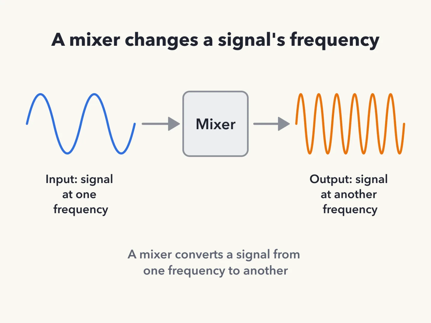
The Mixer Changes Frequency
A mixer converts a signal from one frequency to another.
The Oscillator Makes a Frequency
An oscillator is a circuit that generates a signal at a specific frequency.
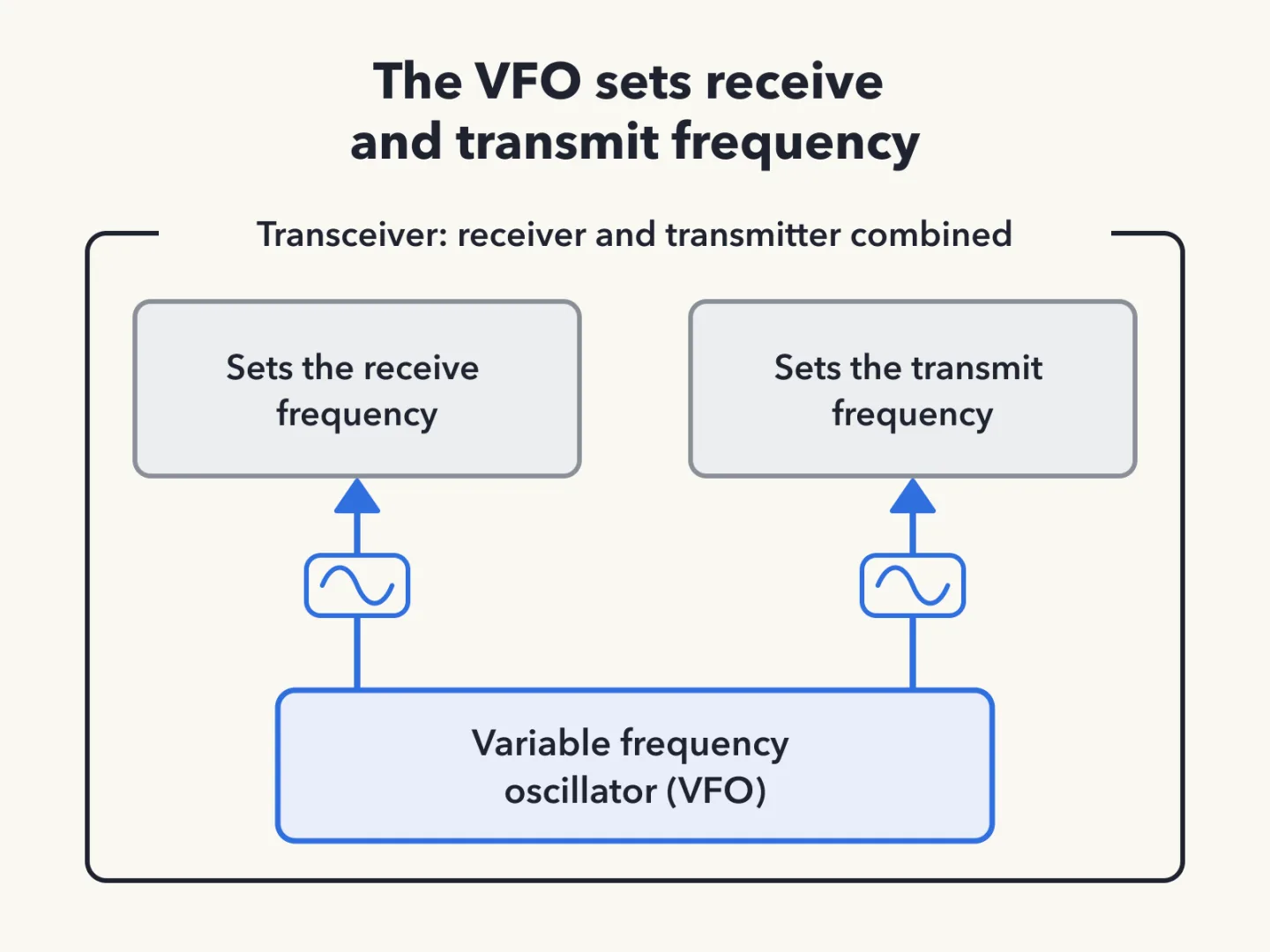
What the VFO Does
The variable frequency oscillator (VFO) in a transceiver sets the receive and transmit frequency.
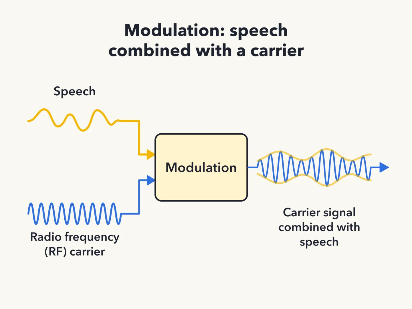
Modulation Puts Speech on a Carrier
Modulation is combining speech with a radio frequency (RF) carrier signal.
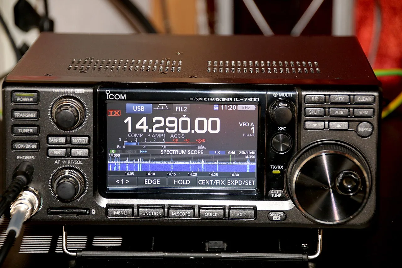
A Transceiver Is Two Radios in One
A transceiver is a device that combines a receiver and a transmitter.
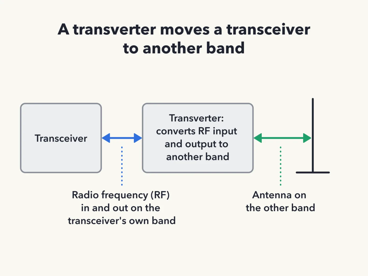
A Transverter Shifts Bands
A transverter is the device that converts the radio frequency (RF) input and output of a transceiver to another band. That is how a transceiver can work on a band it does not cover itself.
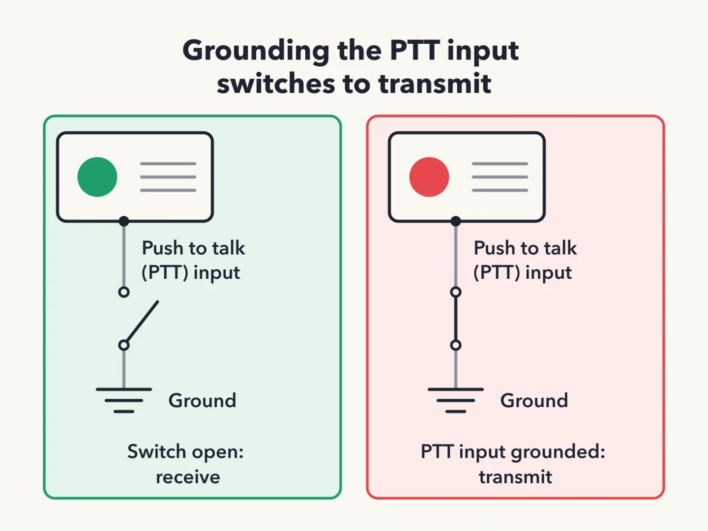
The PTT Input Switches to Transmit
A transceiver's push to talk (PTT) input switches the transceiver from receive to transmit when it is grounded.
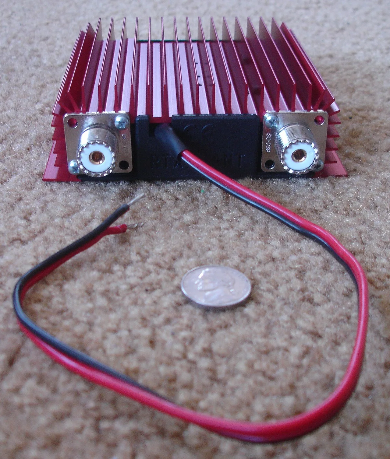
Adding a Power Amplifier
A radio frequency (RF) power amplifier added to the output of a transceiver increases the transmitted output power.
Amplifier Mode Switch
Some very high frequency (VHF) power amplifiers have a switch that selects either single sideband (SSB) or CW-FM, where CW means International Morse code telegraphy emissions and FM stands for frequency modulated. That switch sets the amplifier for proper operation in the selected mode.
Why Broadcast Radios Hear Hams
A broadcast amplitude modulated (AM) or frequency modulated (FM) radio can pick up an amateur transmission unintentionally. The cause is that the receiver is unable to reject strong signals outside the AM or FM band.
Three Causes of Interference
Radio frequency (RF) interference can come from several sources. Fundamental overload, harmonics and spurious emissions can each cause it. All three are correct causes.
High SWR and Low Power
High standing wave ratio (SWR) might be the cause of low radio frequency (RF) power output from a solid-state transceiver.
Filter at the Affected Receiver
To reduce interference from an amateur station to a non-amateur over-the-air receiver, put a filter at the antenna input of the affected receiver. It blocks the amateur signal.
First Response to a Neighbor's Complaint
When a neighbor reports interference to radio or TV, the operator should first make sure the station is functioning properly. It should not interfere with the operator's own radio or television on the same channel.
Band-Reject Filter Against FM Stations
A band-reject filter can reduce interference to a 2-meter band transceiver from a nearby commercial frequency modulated (FM) station.
A Neighbor's Device Interferes
If something in a neighbor's home causes harmful interference to an amateur station, three responses are correct. Work with the neighbor to identify the offending device. Politely inform the neighbor that Federal Communications Commission (FCC) rules prohibit the use of devices that cause interference. Make sure the station meets the standards of good amateur practice.
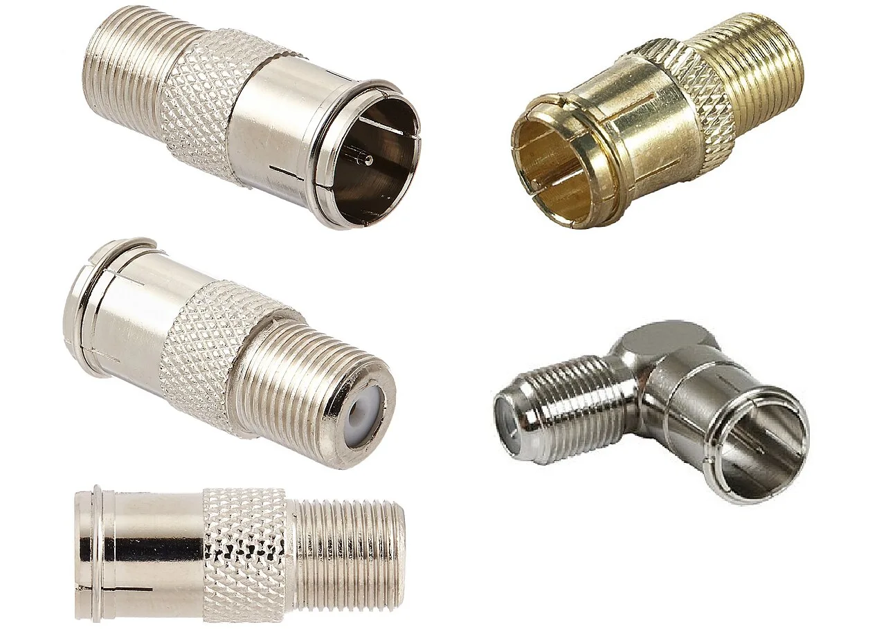
First Step for Cable TV Interference
For interference to non-fiber optic cable TV, the first step is to be sure all TV feed line coaxial connectors are installed properly.
Curing Over-Deviation
A report that a frequency modulated (FM) handheld or mobile transceiver is over-deviating is answered by talking farther away from the microphone.
Distorted Audio Through a Repeater
If a report says audio through a frequency modulated (FM) repeater is distorted or unintelligible, three causes are all correct. The transmitter may be slightly off frequency. The operator may be speaking too loudly or too close to the microphone. The operator may also be in a bad location.
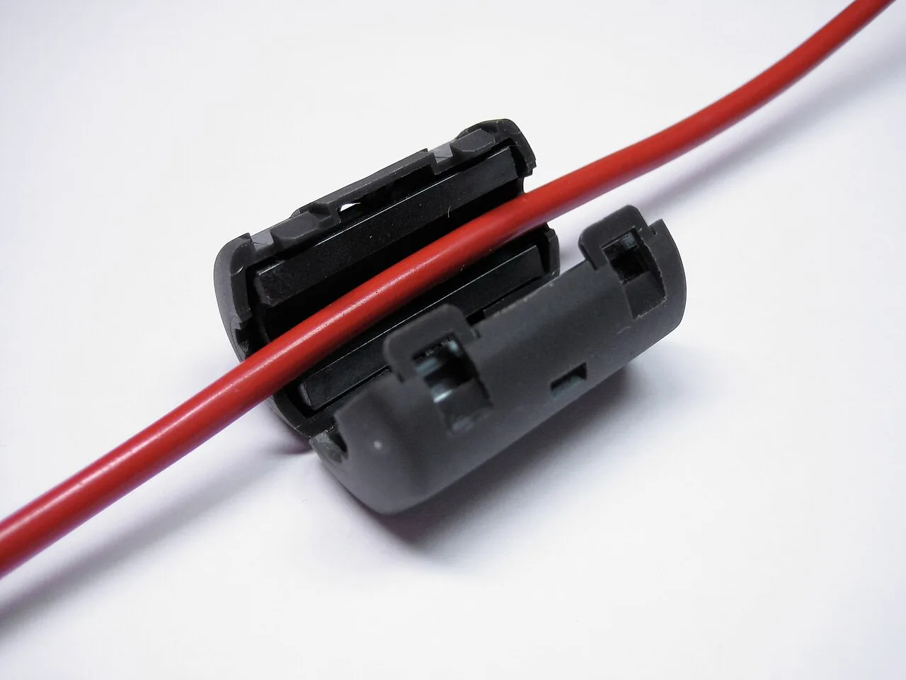
Ferrite Choke on the Mic Cable
A clip-on ferrite choke on the microphone cable can eliminate distorted voice transmissions. It prevents the transmitted signal from feeding back into the transmitter.
Matched pairs
Each item on the left goes with the one on the right.
- Transverter
- Converts a transceiver to another band
- Transceiver
- Combines a receiver and a transmitter
- Over-deviation
- Talk farther from the microphone
Self-test
Answer each question from memory, then check your work against the answer key.
1. Which term describes the ability of a receiver to detect the presence of a signal?
- ASensitivity
- BSelectivity
- CTotal Harmonic Distortion
- DRF gain
2. Which term describes the ability of a receiver to discriminate between multiple signals?
- AHarmonic distortion
- BSelectivity
- CDiscrimination ratio
- DSensitivity
3. Which of the following is used to convert a signal from one frequency to another?
- APhase splitter
- BInverter
- CMixer
- DAmplifier
4. What is the name of a circuit that generates a signal at a specific frequency?
- ALow-pass filter
- BReactance modulator
- CPhase modulator
- DOscillator
5. What is the function of the Variable Frequency Oscillator (VFO) circuit in a transceiver?
- ASet the receive and transmit frequency
- BInject a variable frequency to allow CW reception
- CGenerate and demodulate single sideband signals
- DProvide automatic frequency control
6. Which of the following describes combining speech with an RF carrier signal?
- AOscillation
- BImpedance matching
- CModulation
- DLow-pass filtering
7. What is a transceiver?
- AA device for matching feed line impedance to 50 ohms
- BA device that combines a receiver and transmitter
- CA device for automatically sending and decoding Morse code
- DA device for converting receiver and transmitter frequencies to another band
8. What device converts the RF input and output of a transceiver to another band?
- ALow-pass filter
- BPhase converter
- CHigh-pass filter
- DTransverter
9. What is the function of a transceiver’s PTT input?
- AInput for a preamplifier tuning tone
- BSwitches transceiver from receive to transmit when grounded
- CProvides a transmit tuning tone when grounded
- DInput for a key used to send CW
10. What is the function of the switch which selects either SSB or CW-FM on some VHF power amplifiers?
- ASet the amplifier for proper operation in the selected mode
- BChange the frequency range of the amplifier to operate in the proper segment of the band
- CChange the mode of the transmitted signal
- DReduce the received signal noise
11. What can be added to the output of a transceiver to increase the transmitted output power?
- AAn impedance multiplier
- BA potentiometer
- CAll these choices are correct
- DAn RF power amplifier
12. What would cause a broadcast AM or FM radio to receive an amateur radio transmission unintentionally?
- AThe deviation of an FM transmitter is set too low
- BThe microphone gain of the transmitter is turned up too high
- CThe receiver is unable to reject strong signals outside the AM or FM band
- DThe audio amplifier of the transmitter is overloaded
13. Which of the following can cause radio frequency interference?
- AAll these choices are correct
- BHarmonics
- CSpurious emissions
- DFundamental overload
14. Which of the following might reduce interference by an amateur station to a non-amateur over-the-air radio receiver?
- ASwitch the transmitter to a narrow-band mode
- BBlock the amateur signal with a filter at the antenna input of the affected receiver
- CBlock the interfering signal with a filter on the amateur transmitter
- DSwitch the transmitter from FM to SSB
15. Which of the following can reduce interference to a 2-meter band transceiver from a nearby commercial FM station?
- AInstalling bypass capacitors on the microphone cable
- BUsing double-shielded coaxial cable
- CInstalling a band-reject filter
- DInstalling an RF preamplifier
16. Which of the following actions should you take if a neighbor tells you that your station’s transmissions are interfering with their radio or TV reception?
- AImmediately turn off your transmitter and contact the nearest FCC office for assistance
- BAll these choices are correct
- CInstall a harmonic doubler on the transmitter output and tune until interference stops
- DMake sure station works properly, doesn't interfere with own radio or TV on same channel
17. What should be the first step to resolve non-fiber optic cable TV interference caused by your amateur radio transmission?
- AAdd a low-pass filter to the TV antenna input
- BBe sure all TV feed line coaxial connectors are installed properly
- CAdd a high-pass filter to the TV antenna input
- DAdd a preamplifier to the TV antenna input
18. What can you do if you are told your FM handheld or mobile transceiver is over-deviating?
- ATalk farther away from the microphone
- BLet the transceiver cool off
- CTalk louder into the microphone
- DChange to a higher power level
19. What might be a problem if you receive a report that your audio signal through an FM repeater is distorted or unintelligible?
- AYou are speaking too loudly or too close to the microphone
- BYour transmitter is slightly off frequency
- CYou are in a bad location
- DAll these choices are correct
20. Which of the following might be the cause of low RF power output from a solid-state transceiver?
- APoor amplifier noise figure
- BLow SWR
- CHigh SWR
- DPoor amplifier linearity
21. What should you do if something in a neighbor’s home is causing harmful interference to your amateur station?
- AMake sure your station meets the standards of good amateur practice
- BPolitely tell your neighbor FCC rules prohibit devices that cause interference
- CWork with your neighbor to identify the offending device
- DAll these choices are correct
22. Which of the following can eliminate distorted voice transmissions?
- AAdding extra feedline to the antenna to lower SWR
- BTurning squelch fully clockwise to stop the transmitted signal triggering squelch
- CAdding a clip-on ferrite “choke” on mic cable to stop transmitted signal feeding back
- DTurning the radio on and off to reset the computer-controlled circuitry
Go deeper
- ListenLesson 10 episode
- WatchWhy a Broadcast Radio Picks Up a Ham Imagine an amateur station is on the air, and a broadcast radio picks up its signal. Nobody meant it to happen.
- WatchHow a Transceiver Reaches Another Band A transceiver covers certain bands on its own. Could it work a band it does not cover?
- StudyHam Radio Technician License in the FlashFeed app
Answer key
- 1. A SensitivitySensitivity is the ability of a receiver to detect the presence of a signal. Selectivity is a different property: telling signals apart. RF stands for radio frequency.
- 2. B SelectivitySelectivity is the ability of a receiver to discriminate between multiple signals, picking one out from several.
- 3. C MixerA mixer converts a signal from one frequency to another. A phase splitter, inverter and amplifier do not.
- 4. D OscillatorAn oscillator is a circuit that generates a signal at a specific frequency.
- 5. A Set the receive and transmit frequencyThe VFO in a transceiver sets the receive and transmit frequency. CW stands for continuous wave.
- 6. C ModulationModulation is combining speech with a radio frequency (RF) carrier signal.
- 7. B A device that combines a receiver and transmitterA transceiver is a device that combines a receiver and a transmitter.
- 8. D TransverterA transverter converts the radio frequency (RF) input and output of a transceiver to another band. Filters do not convert frequencies.
- 9. B Switches transceiver from receive to transmit when groundedThe push to talk (PTT) input switches the transceiver from receive to transmit when grounded. CW stands for continuous wave.
- 10. A Set the amplifier for proper operation in the selected modeThe switch sets the amplifier for proper operation in the selected mode. It does not change the transmitted signal's mode. SSB stands for single sideband and VHF stands for very high frequency.
- 11. D An RF power amplifierA radio frequency (RF) power amplifier added to the output increases transmitted power. A potentiometer and impedance multiplier do not, so all-correct is wrong.
- 12. C The receiver is unable to reject strong signals outside the AM or FM bandA broadcast receiver hears a ham because it cannot reject strong signals outside the amplitude modulated (AM) or frequency modulated (FM) band. High microphone gain is not the cause.
- 13. A All these choices are correctFundamental overload, harmonics and spurious emissions can each cause radio frequency interference, so all are correct.
- 14. B Block the amateur signal with a filter at the antenna input of the affected receiverA filter at the antenna input of the affected receiver blocks the amateur signal. Mode changes are not the answer. FM stands for frequency modulated and SSB stands for single sideband.
- 15. C Installing a band-reject filterA band-reject filter can reduce interference from a nearby commercial frequency modulated (FM) station. A preamplifier or shielded cable is not the remedy. RF stands for radio frequency.
- 16. D Make sure station works properly, doesn't interfere with own radio or TV on same channelFirst make sure the station works properly and does not interfere with the operator's own radio or TV on the same channel. FCC stands for Federal Communications Commission.
- 17. B Be sure all TV feed line coaxial connectors are installed properlyFor non-fiber optic cable TV, first be sure all TV feed line coaxial connectors are installed properly.
- 18. A Talk farther away from the microphoneOver-deviation is cured by talking farther away from the microphone. Talking louder is not the cure. FM stands for frequency modulated.
- 19. D All these choices are correctBeing off frequency, speaking too loudly or too close to the microphone, and a bad location can each distort repeater audio. All are correct. FM stands for frequency modulated.
- 20. C High SWRHigh standing wave ratio (SWR) might cause low radio frequency (RF) power output from a solid-state transceiver. Low SWR is not a cause.
- 21. D All these choices are correctWork with the neighbor to find the device, politely note Federal Communications Commission (FCC) rules, and ensure good amateur practice. All three are correct.
- 22. C Adding a clip-on ferrite “choke” on mic cable to stop transmitted signal feeding backA clip-on ferrite choke on the microphone cable keeps the transmitted signal from feeding back into the transmitter. SWR stands for standing wave ratio.
Sources
- NCVEC Question Pool Committee — 2026–2030 Technician question pool — ncvec.org/index.php/2026-2030-technician-question-pool
- FCC — 47 CFR § 97.3 Definitions — www.ecfr.gov/current/title-47/section-97.3
Image credits
- Sensitivity: Detecting a Signal: FlashFeed original diagram · CC-BY-4.0
- The Mixer Changes Frequency: FlashFeed original diagram · CC-BY-4.0
- What the VFO Does: FlashFeed original diagram · CC-BY-4.0
- Modulation Puts Speech on a Carrier: FlashFeed original diagram · CC-BY-4.0
- A Transceiver Is Two Radios in One: Wikimedia Commons · Hp.Baumeler · CC BY-SA 4.0 — commons.wikimedia.org/wiki/File:IC-7300.jpg
- A Transverter Shifts Bands: FlashFeed original diagram · CC-BY-4.0
- The PTT Input Switches to Transmit: FlashFeed original diagram · CC-BY-4.0
- Adding a Power Amplifier: Wikimedia Commons · Zuzu · CC BY-SA 3.0 — commons.wikimedia.org/wiki/File:RM_Italy_KL-203_linear_amplifier_rear_with_unfused_power_cable.jpeg
- Amplifier Mode Switch: FlashFeed original diagram · CC-BY-4.0
- Why Broadcast Radios Hear Hams: FlashFeed original diagram · CC-BY-4.0
- Filter at the Affected Receiver: FlashFeed original diagram · CC-BY-4.0
- Band-Reject Filter Against FM Stations: FlashFeed original diagram · CC-BY-4.0
- First Step for Cable TV Interference: Wikimedia Commons · Eyreland · CC BY-SA 4.0 — commons.wikimedia.org/wiki/File:Flex_Coax_Connector_F_Type.jpg
- Ferrite Choke on the Mic Cable: Wikimedia Commons · Karl-Martin Skontorp · CC BY 2.0 — commons.wikimedia.org/wiki/File:Ferrite_clamp-on.jpg


