
Ham Radio Technician License study guide · Lesson 11 of 15
Practical Circuits: Measuring and Testing
Measuring and troubleshooting antennas and lines · Test meters and soldering
This is the lesson's study guide from the FlashFeed app, plus its key facts and a self-test.
What you'll be able to do
- Explain how dummy loads, antenna analyzers and directional wattmeters are used, and what SWR readings such as 1:1 and 4:1 mean
- Describe the effects of high SWR, where feed line loss goes, why coaxial cable fails, and the advantage of foam-dielectric coax
- Identify the meters for voltage, current and resistance, how each connects to a circuit, and how an ohmmeter measures resistance
- Explain safe multimeter and ohmmeter use, what an ohmmeter shows across a capacitor, and how to choose solder and judge joints
This lesson covers the instruments and habits used to check a station. The first half deals with antennas and feed lines: dummy loads, standing wave ratio (SWR) readings, coaxial cable and why it fails. The second half deals with test meters and solder: what each meter measures, how it connects, and what a good solder joint looks like. A new licensee who knows these points can test equipment without damaging it and can tell a sound connection from a poor one.
Measuring and troubleshooting antennas and lines
Dummy loads
A dummy load lets a transmitter be tested without putting a signal on the air. Its primary purpose is to prevent transmitting signals over the air when making tests.
A typical radio frequency (RF) dummy load consists of a 50-ohm non-inductive resistor mounted on a heat sink. A new licensee who connects a dummy load is, in effect, giving the transmitter a resistor to work into instead of an antenna.
Resonance and SWR readings
An antenna analyzer is the instrument used to determine whether an antenna is resonant at the desired operating frequency.
The standing wave ratio (SWR) is read on an SWR meter as a ratio. A reading of 1:1 indicates a perfect impedance match between the antenna and the feed line. A reading of 4:1 indicates an impedance mismatch.
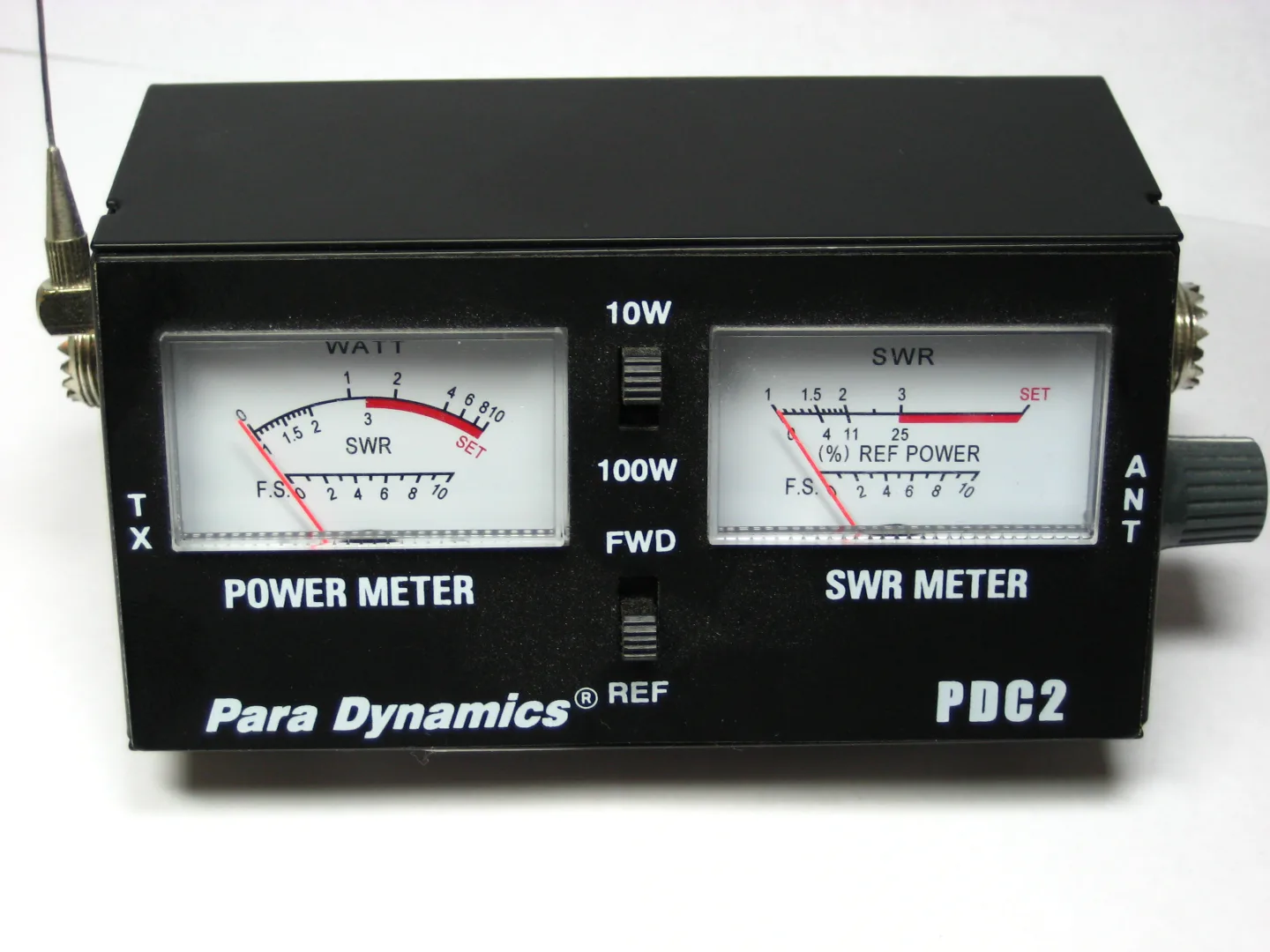
A directional wattmeter can be used to determine SWR.
What high SWR does
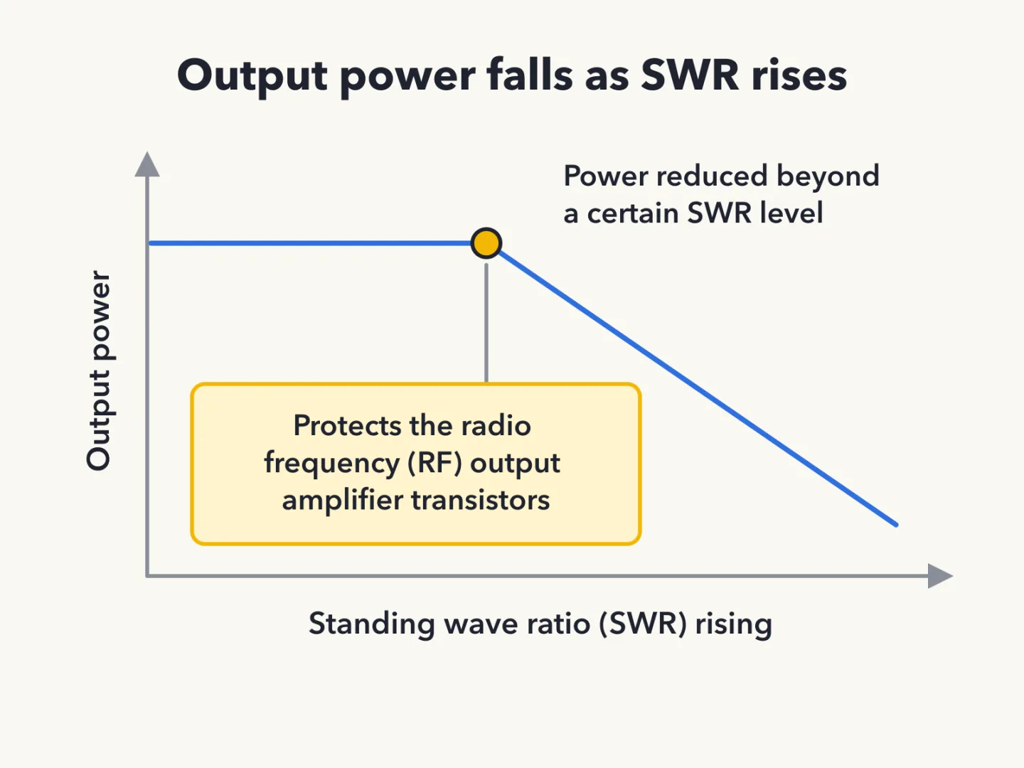
Most solid-state transmitters reduce output power as SWR increases beyond a certain level. The reduction protects the RF output amplifier transistors.
Feed line loss and coax failure
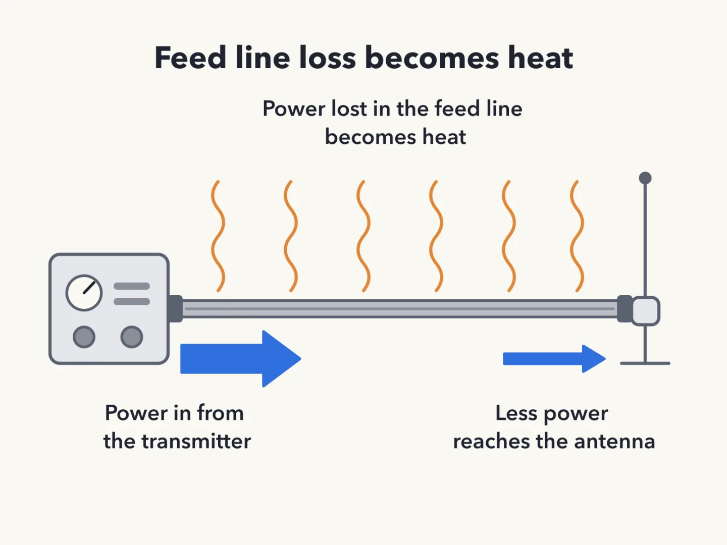
Power lost in a feed line is converted into heat.
Moisture contamination causes failure of coaxial cables.
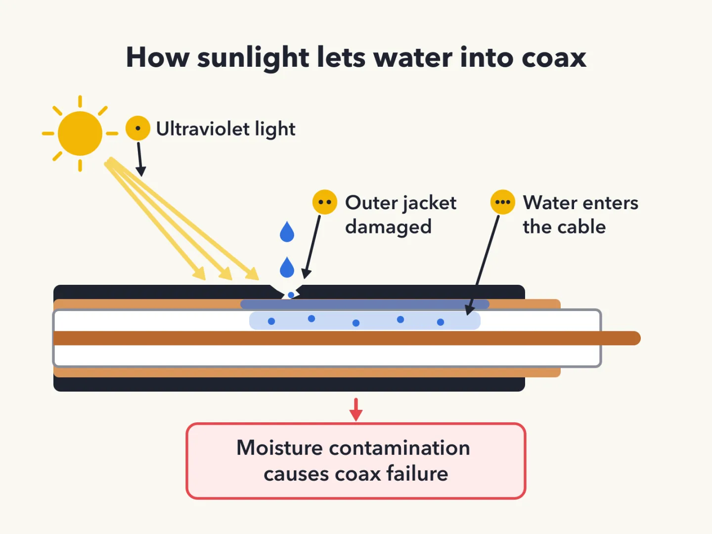
This is also why the outer jacket of coaxial cable should be resistant to ultraviolet light. Ultraviolet light can damage the jacket and allow water to enter the cable. A cable with a sound jacket keeps water out, and water getting in is the failure to avoid.
When choosing between cables, a foam-dielectric coaxial cable has an advantage over a solid-dielectric one: it has less loss per foot.
Sources
Test meters and soldering
What each meter measures
A voltmeter measures electric potential, which is the voltage across a part. An ammeter measures electric current. An ohmmeter measures resistance.
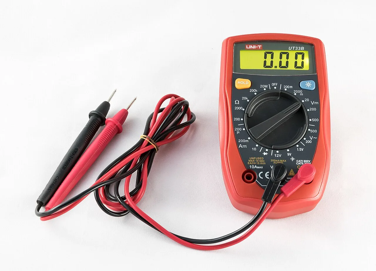
A multimeter combines these functions in one instrument. Voltage and resistance are among the measurements made using a multimeter. When it is configured to measure current, a multimeter works as an ammeter.
How meters connect
A voltmeter is connected to a component in parallel to measure applied voltage. A multimeter configured to measure current is connected to the component in series. A new licensee reading a voltage connects the meter in parallel, then switches to the current setting and connects it in series to read a current.
How an ohmmeter works
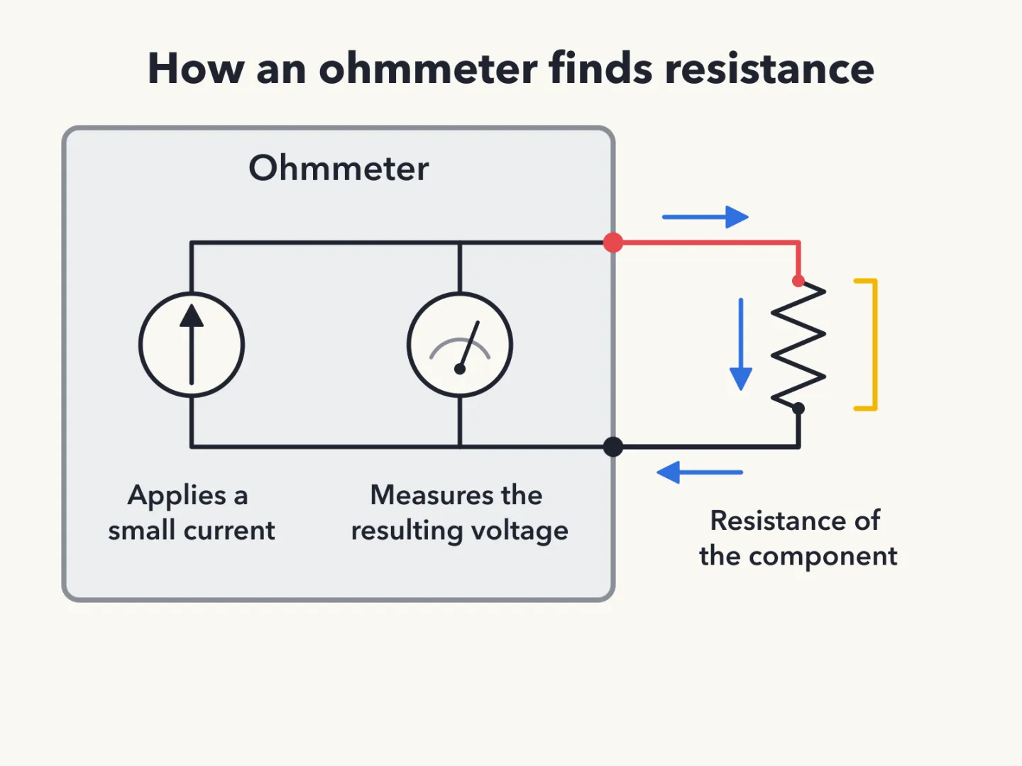
An ohmmeter measures the resistance of a circuit or component by applying a small current and measuring the resulting voltage.
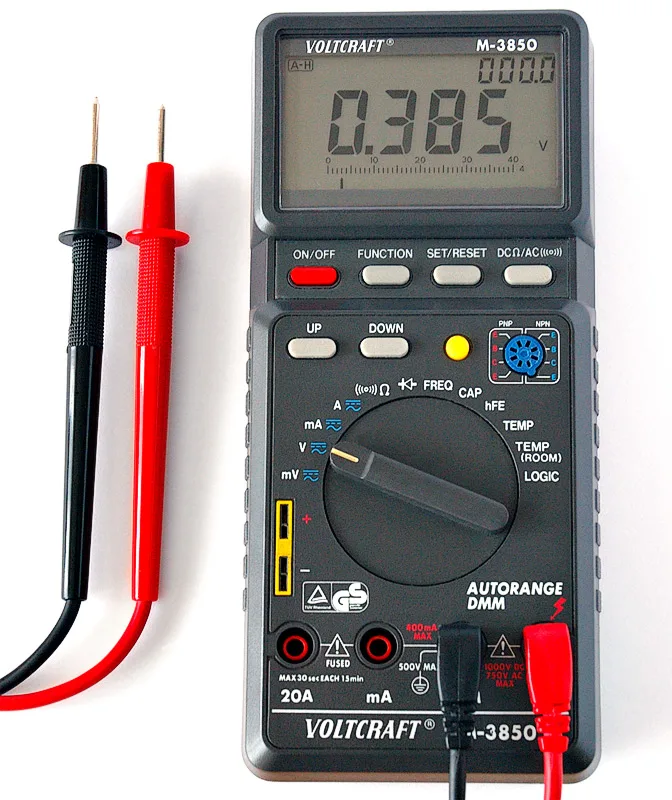
Two precautions follow from careful use. Attempting to measure voltage when using the resistance setting can damage a multimeter. When measuring in-circuit resistance with an ohmmeter, the circuit must not be powered.
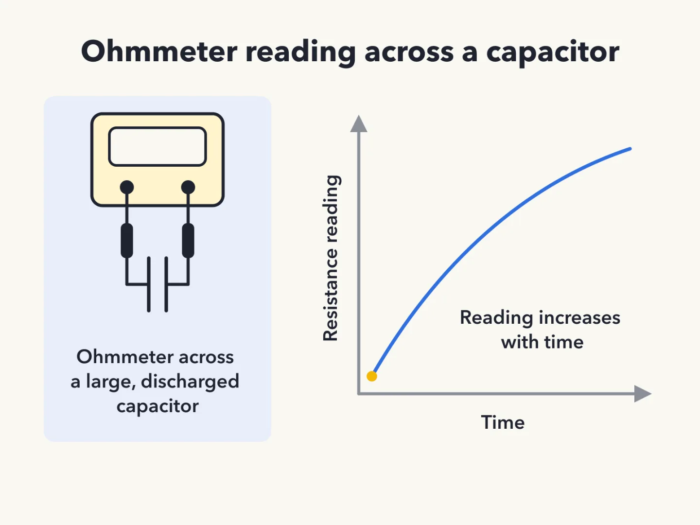
An ohmmeter connected across a large, discharged capacitor shows increasing resistance with time.
Solder and joints
Acid-core solder should not be used for radio and electronic applications. A licensee soldering a connection therefore chooses rosin-core solder rather than acid-core.
A cold solder joint made with tin-lead solder has a rough or lumpy surface. A joint that comes out rough or lumpy is the one to suspect.
Sources
Key facts
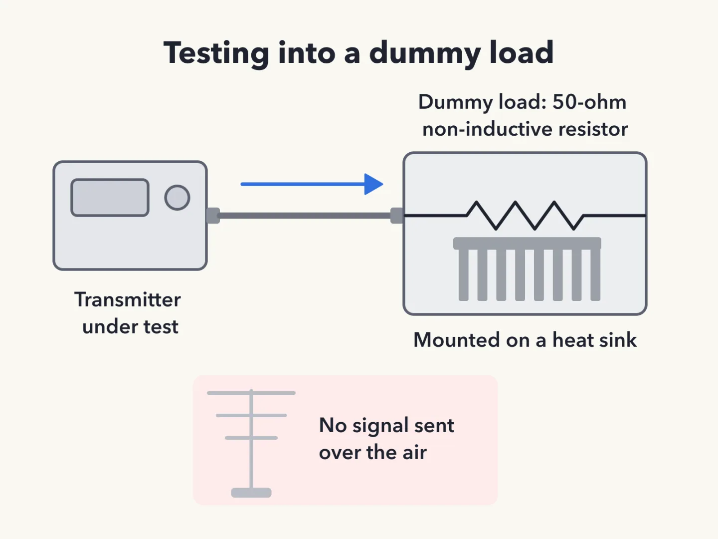
Why Use a Dummy Load
A dummy load lets a transmitter be tested without putting a signal on the air. Its primary purpose is to prevent transmitting signals over the air when making tests.
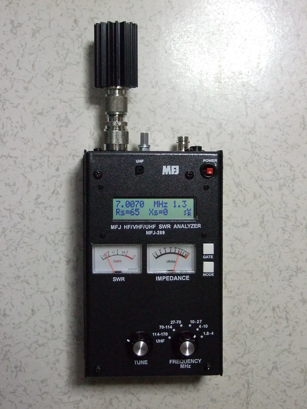
Checking Antenna Resonance
An antenna analyzer is the instrument used to determine whether an antenna is resonant at the desired operating frequency.
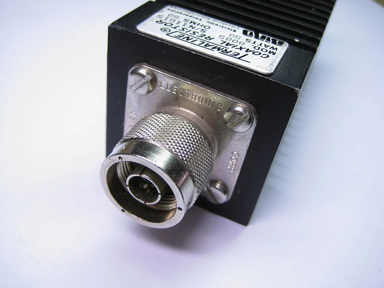
What a Dummy Load Is Made Of
A typical radio frequency (RF) dummy load consists of a 50-ohm non-inductive resistor mounted on a heat sink.
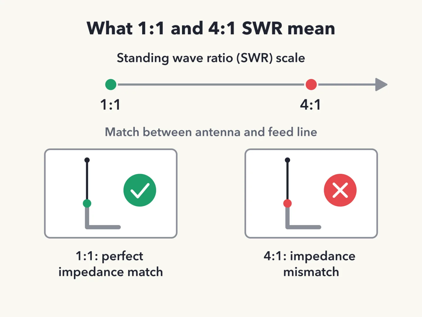
SWR of 1:1 Means a Match
The standing wave ratio (SWR) is read on an SWR meter as a ratio. A reading of 1:1 indicates a perfect impedance match between the antenna and the feed line.
Why Transmitters Cut Power
Most solid-state transmitters reduce output power as standing wave ratio (SWR) increases beyond a certain level. The reduction protects the radio frequency (RF) output amplifier transistors.
SWR of 4:1 Means Mismatch
A standing wave ratio (SWR) reading of 4:1 indicates an impedance mismatch.
Where Lost Power Goes
Power lost in a feed line is converted into heat.
Instrument That Finds SWR
A directional wattmeter can be used to determine standing wave ratio (SWR).
What Makes Coax Fail
Moisture contamination causes failure of coaxial cables.
Why Coax Jackets Resist Sunlight
The outer jacket of coaxial cable should be resistant to ultraviolet light. Ultraviolet light can damage the jacket and allow water to enter the cable.
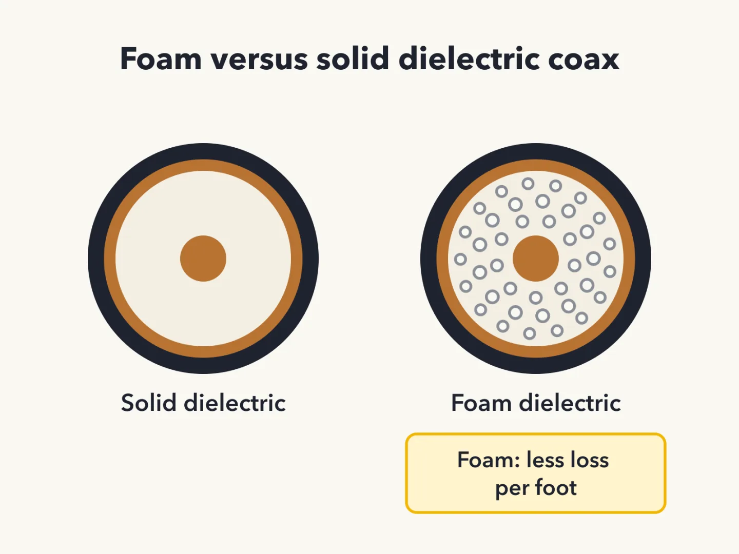
Foam Versus Solid Dielectric
A foam-dielectric coaxial cable has less loss per foot than a solid-dielectric one.
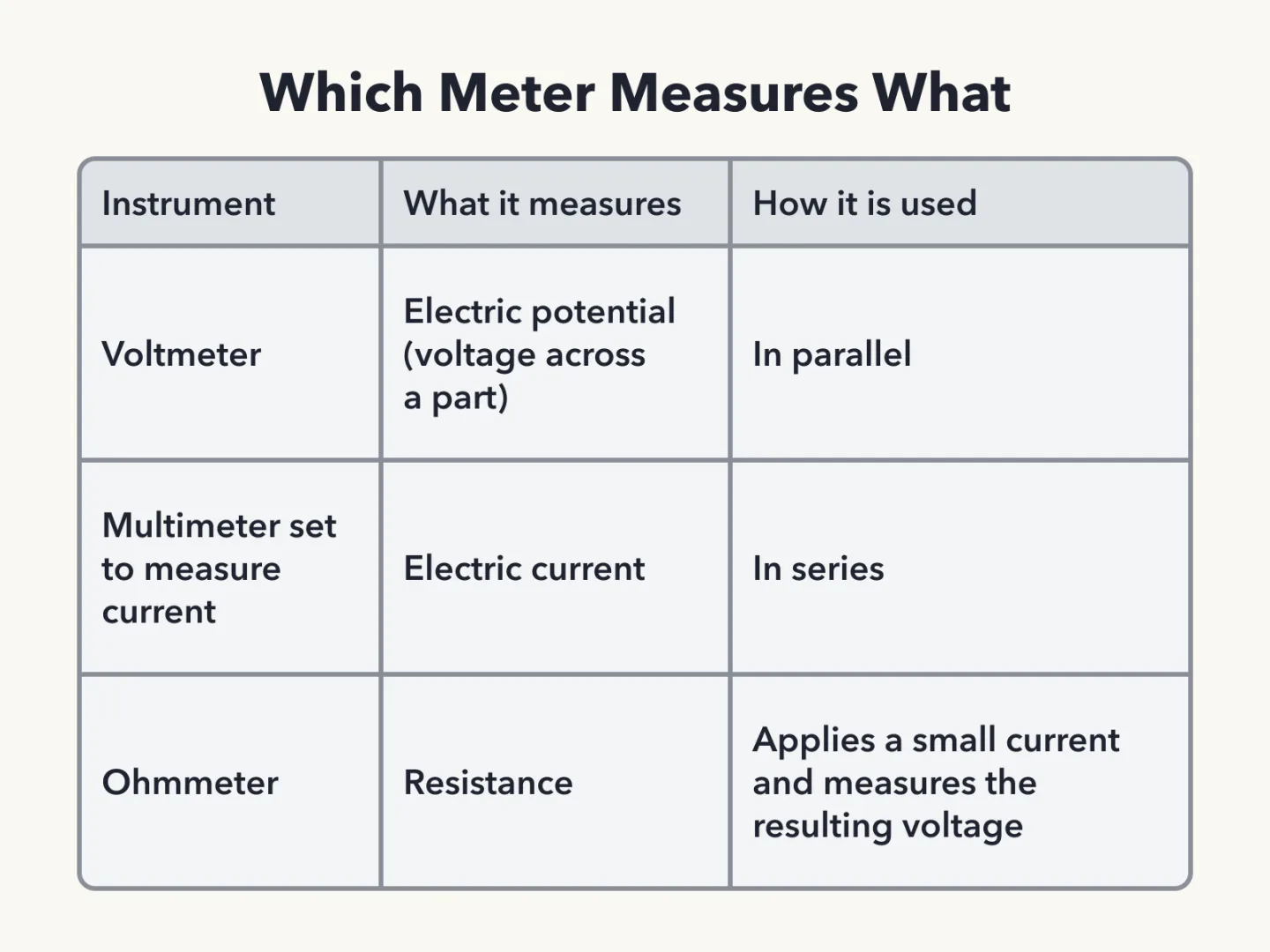
Voltmeter Measures Potential
A voltmeter measures electric potential, which is the voltage across a part.
Voltmeters Connect in Parallel
A voltmeter is connected to a component in parallel to measure applied voltage.
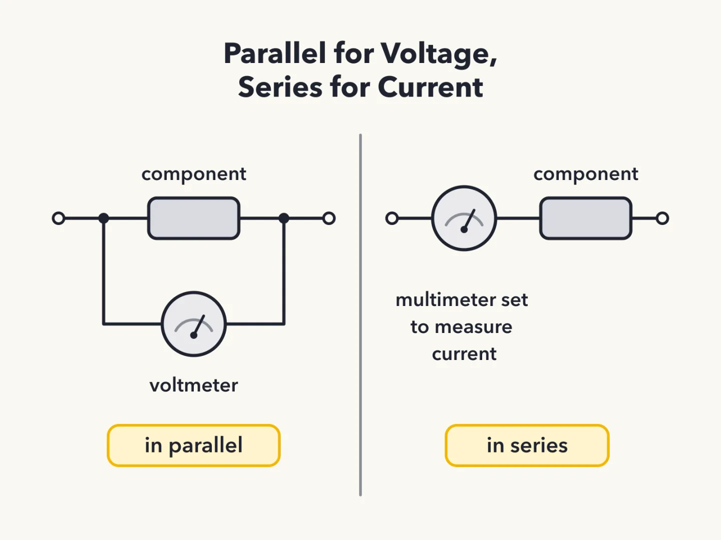
Current Readings Use Series
A multimeter configured to measure current is connected to the component in series.
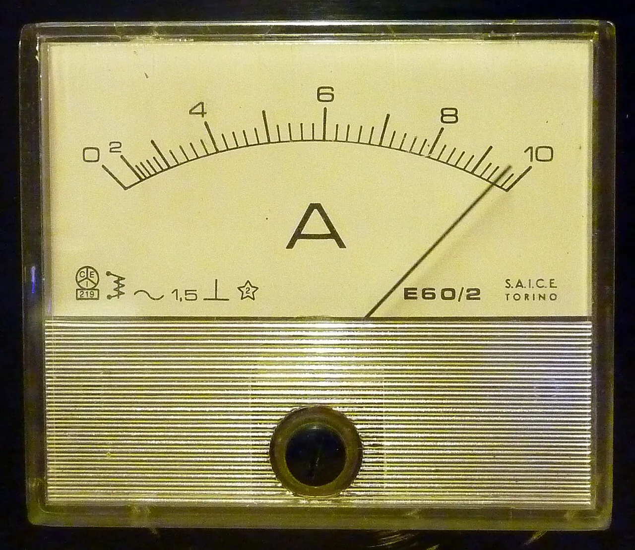
Ammeter Measures Current
An ammeter measures electric current.
How an Ohmmeter Works
An ohmmeter measures the resistance of a circuit or component by applying a small current and measuring the resulting voltage.
What Damages a Multimeter
Attempting to measure voltage when using the resistance setting can damage a multimeter.
What a Multimeter Measures
A multimeter combines meter functions in one instrument. Voltage and resistance are among the measurements made using a multimeter, and it can also be configured to measure current.
Solder to Avoid
Acid-core solder should not be used for radio and electronic applications.
Spotting a Cold Solder Joint
A cold solder joint made with tin-lead solder has a rough or lumpy surface.
Ohmmeter Across a Capacitor
An ohmmeter connected across a large, discharged capacitor shows increasing resistance with time.
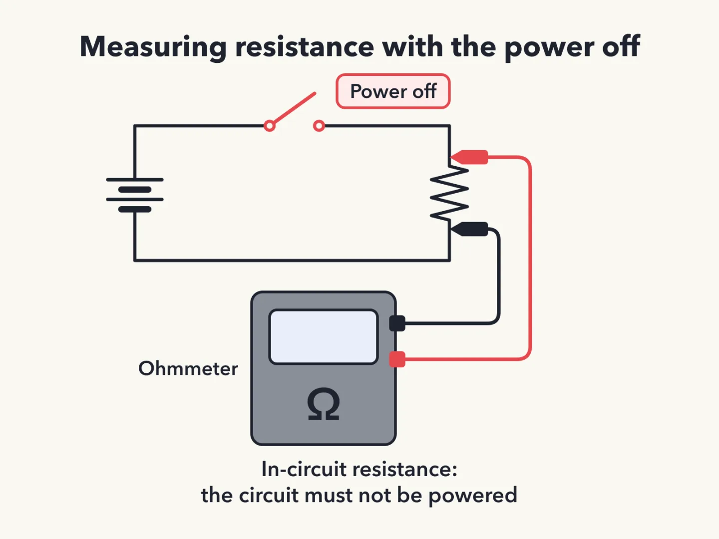
Unpowered for Resistance Checks
When measuring in-circuit resistance with an ohmmeter, the circuit must not be powered.
Matched pairs
Each item on the left goes with the one on the right.
- Dummy load
- 50-ohm non-inductive resistor on a heat sink
- Voltmeter
- Measures electric potential
Self-test
Answer each question from memory, then check your work against the answer key.
1. What is the primary purpose of a dummy load?
- ATo improve the efficiency of an antenna
- BTo prevent transmitting signals over the air when making tests
- CTo prevent over-modulation of a transmitter
- DTo improve the signal-to-noise ratio of a receiver
2. What does a typical RF dummy load consist of?
- AA 50-ohm inductive reactance mounted in a shielded enclosure
- BA low-voltage power supply and a DC relay
- CA 50-ohm non-inductive resistor mounted on a heat sink
- DA low-voltage power supply and an AC relay
3. Which of the following is used to determine if an antenna is resonant at the desired operating frequency?
- AAn antenna analyzer
- BA VTVM
- CA frequency counter
- DA Q meter
4. Which instrument can be used to determine SWR?
- AVoltmeter
- BIambic pentameter
- COhmmeter
- DDirectional wattmeter
5. What reading on an SWR meter indicates a perfect impedance match between the antenna and the feed line?
- AZero
- BFull Scale
- C50:50
- D1:1
6. What does an SWR reading of 4:1 indicate?
- AImpedance mismatch
- BGood impedance match
- CLoss of -4 dB
- DGain of +4 dB
7. Why do most solid-state transmitters reduce output power as SWR increases beyond a certain level?
- ABecause power supplies cannot supply enough current at high SWR
- BTo protect the RF output amplifier transistors
- CTo comply with FCC rules on spectral purity
- DTo lower the SWR on the transmission line
8. What happens to power lost in a feed line?
- AIt increases the SWR
- BIt is radiated as harmonics
- CIt is converted into heat
- DIt distorts the signal
9. Which of the following causes failure of coaxial cables?
- AOperation at 100% duty cycle for an extended period
- BSolder flux contamination
- CMoisture contamination
- DRapid fluctuation in transmitter output power
10. Why should the outer jacket of coaxial cable be resistant to ultraviolet light?
- AUltraviolet light can damage the jacket and allow water to enter the cable
- BUltraviolet light can increase the resistance of the conductors
- CUltraviolet light can increase losses in the cable’s jacket
- DUltraviolet and RF signals can mix, causing interference
11. What is an advantage of foam-dielectric versus solid-dielectric coaxial cable?
- AIt is more resistant to moisture contamination
- BIt has less loss per foot
- CIt has a better impedance match to 50 ohms
- DIt has higher voltage breakdown
12. Which instrument would you use to measure electric potential?
- AAn ammeter
- BAn ohmmeter
- CA potentiometer
- DA voltmeter
13. Which instrument is used to measure electric current?
- AAn ohmmeter
- BAn ammeter
- CAn electrometer
- DA voltmeter
14. Which of the following measurements are made using a multimeter?
- AVoltage and resistance
- BAll these choices are correct
- CImpedance and reactance
- DSignal strength and noise
15. How is a voltmeter connected to a component to measure applied voltage?
- AIn phase
- BIn quadrature
- CIn series
- DIn parallel
16. When configured to measure current, how is a multimeter connected to a component?
- AIn parallel
- BIn phase
- CIn series
- DIn quadrature
17. How does an ohmmeter measure the resistance of a circuit or component?
- ABy applying a small current and measuring the resulting voltage
- BBy placing a variable resistor in parallel with the circuit
- CBy placing a variable resistor in series with the circuit
- DBy applying a variable voltage and measuring the resulting current change
18. Which of the following can damage a multimeter?
- AFailing to connect one of the probes to ground
- BNot allowing it to warm up properly
- CAttempting to measure resistance using the voltage setting
- DAttempting to measure voltage when using the resistance setting
19. What reading indicates that an ohmmeter is connected across a large, discharged capacitor?
- ASteady full-scale reading
- BIncreasing resistance with time
- CDecreasing resistance with time
- DAlternating between open and short circuit
20. Which of the following precautions should be taken when measuring in-circuit resistance with an ohmmeter?
- AEnsure that the applied voltages are correct
- BEnsure that the circuit is grounded
- CEnsure that the circuit is not powered
- DEnsure that the circuit is operating at the correct frequency
21. Which of the following types of solder should not be used for radio and electronic applications?
- ATin-copper solder
- BLead-tin solder
- CRosin-core solder
- DAcid-core solder
22. What is the characteristic appearance of a cold tin-lead solder joint?
- AA bright or shiny surface
- BA greenish tinge
- CA rough or lumpy surface
- DDark black spots
Go deeper
- ListenLesson 11 episode
- WatchWhy Transmitters Cut Their Own Power Why would a transmitter turn its own power down, even while it is still on the air?
- WatchWhich Setting Can Damage a Multimeter Which simple mistake can damage a multimeter when it is being used?
- StudyHam Radio Technician License in the FlashFeed app
Answer key
- 1. B To prevent transmitting signals over the air when making testsA dummy load lets a transmitter be tested without putting a signal on the air. It does not prevent over-modulation or improve antennas or receivers.
- 2. C A 50-ohm non-inductive resistor mounted on a heat sinkA typical radio frequency (RF) dummy load is a 50-ohm non-inductive resistor on a heat sink, not a power supply with a relay or an inductive reactance. AC stands for alternating current and DC stands for direct current.
- 3. A An antenna analyzerAn antenna analyzer shows whether an antenna is resonant at the desired operating frequency. A Q meter and frequency counter are not the right tools. VTVM stands for vacuum-tube voltmeter.
- 4. D Directional wattmeterA directional wattmeter can determine standing wave ratio (SWR). A voltmeter and an ohmmeter are not the instruments for that purpose.
- 5. D 1:1A standing wave ratio (SWR) of 1:1 means a perfect impedance match between antenna and feed line. 50:50, zero and full scale do not.
- 6. A Impedance mismatchA 4:1 standing wave ratio (SWR) reading indicates an impedance mismatch. It is not a good match and not a gain or loss in dB.
- 7. B To protect the RF output amplifier transistorsSolid-state transmitters cut power at high standing wave ratio (SWR) to protect the radio frequency (RF) output amplifier transistors. Doing so does not lower the SWR. FCC stands for Federal Communications Commission.
- 8. C It is converted into heatPower lost in a feed line becomes heat. It does not raise standing wave ratio (SWR), radiate as harmonics or distort the signal.
- 9. C Moisture contaminationMoisture contamination causes coax failure. Flux, power fluctuation and long duty cycles are not the cause.
- 10. A Ultraviolet light can damage the jacket and allow water to enter the cableUltraviolet light can damage the jacket and let water in, and water is what fails coax. It does not change conductor resistance or mix with radio frequency (RF).
- 11. B It has less loss per footFoam-dielectric coax has less loss per foot than solid-dielectric. It is not better at moisture, voltage breakdown or 50-ohm match.
- 12. D A voltmeterA voltmeter measures electric potential, the voltage across a part. An ammeter measures current, an ohmmeter measures resistance, and in radio work a potentiometer is a variable resistor rather than a meter.
- 13. B An ammeterAn ammeter measures electric current. An ohmmeter, electrometer and voltmeter are not the instrument for it.
- 14. A Voltage and resistanceA multimeter measures voltage and resistance. Signal strength, noise, impedance and reactance are not its measurements.
- 15. D In parallelA voltmeter connects in parallel with the component to measure applied voltage, not in series, quadrature or phase.
- 16. C In seriesA multimeter set to measure current connects in series with the component, not in parallel.
- 17. A By applying a small current and measuring the resulting voltageAn ohmmeter applies a small current and measures the resulting voltage. It does not use a variable resistor or a variable voltage.
- 18. D Attempting to measure voltage when using the resistance settingTrying to measure voltage on the resistance setting can damage a multimeter. The other listed actions do not.
- 19. B Increasing resistance with timeAcross a large, discharged capacitor an ohmmeter shows increasing resistance with time, not decreasing, steady or alternating readings.
- 20. C Ensure that the circuit is not poweredFor in-circuit resistance, the circuit must not be powered. Checking voltages, grounding or frequency are not the precautions.
- 21. D Acid-core solderAcid-core solder should not be used for radio and electronic work. Lead-tin, rosin-core and tin-copper are not the types to avoid.
- 22. C A rough or lumpy surfaceA cold tin-lead joint has a rough or lumpy surface. A bright or shiny surface is not its mark.
Sources
- NCVEC Question Pool Committee — 2026–2030 Technician question pool — ncvec.org/index.php/2026-2030-technician-question-pool
Image credits
- Why Use a Dummy Load: FlashFeed original diagram · CC-BY-4.0
- Checking Antenna Resonance: Wikimedia Commons · しまでん · CC BY-SA 3.0 — commons.wikimedia.org/wiki/File:SWR_analyzer_measuring_a_dummy_load.jpg
- What a Dummy Load Is Made Of: Wikimedia Commons · Karl-Martin Skontorp from Norway · CC BY 2.0 — commons.wikimedia.org/wiki/File:Dummy_load_(detail).jpg
- SWR of 1:1 Means a Match: FlashFeed original diagram · CC-BY-4.0
- Why Transmitters Cut Power: FlashFeed original diagram · CC-BY-4.0
- Where Lost Power Goes: FlashFeed original diagram · CC-BY-4.0
- Instrument That Finds SWR: Wikimedia Commons · Theonlysilentbob at English Wikipedia · CC BY-SA 3.0 — commons.wikimedia.org/wiki/File:Para_dynamics_swrmeter_dec07.jpg
- Why Coax Jackets Resist Sunlight: FlashFeed original diagram · CC-BY-4.0
- Foam Versus Solid Dielectric: FlashFeed original diagram · CC-BY-4.0
- Voltmeter Measures Potential: FlashFeed original diagram · CC-BY-4.0
- Current Readings Use Series: FlashFeed original diagram · CC-BY-4.0
- Ammeter Measures Current: Wikimedia Commons · Lklundin, cropped and color-corrected by Kvng · CC BY-SA 4.0 — commons.wikimedia.org/wiki/File:Moving_iron_ammeter.jpg
- How an Ohmmeter Works: FlashFeed original diagram · CC-BY-4.0
- What Damages a Multimeter: Wikimedia Commons · André Karwath aka Aka · CC BY-SA 2.5 — commons.wikimedia.org/wiki/File:Digital_Multimeter_Aka.jpg
- What a Multimeter Measures: Wikimedia Commons · Jacek Halicki · CC BY-SA 4.0 — commons.wikimedia.org/wiki/File:2017_Cyfrowy_miernik_uniwersalny.jpg
- Ohmmeter Across a Capacitor: FlashFeed original diagram · CC-BY-4.0
- Unpowered for Resistance Checks: FlashFeed original diagram · CC-BY-4.0


